2-26
Hardware Installation Procedure
Coral FlexiCom 6000 Installation Manual
Eq
uipment Insta
llation
2
5.
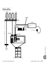
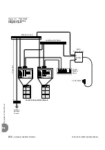
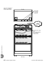
Determine the route of the RJ-45 cable (as shown in
) from the
LAN/WAN/PSTN/router/LTU/CSU to the LDF/UDF panel on the rear section
of the cabinet. Measure the longest distance from the LDF/UDF panel to the
corresponding LAN/WAN/PSTN/router/LTU/CSU connector.
6.
Fabricate a cable of the length determined in
with a male 4 pair RJ-45
connector on each end. For information on the pinout connection, see Chapter
5.9 of the
Coral FlexiCom 300, 400, 5000 Installation Procedure and
Hardware Reference Manual
.
7.
Connect one side of the RJ-45 cable routed in
to the
LAN/WAN/PSTN/router/LTU/CSU/etc.
8.
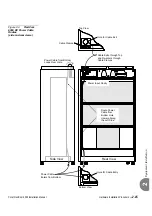
Carefully route the other side of the RJ-45 cable routed in
through one
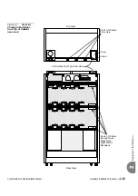
of the three cable entry points in the top rear of the Coral cabinet, as shown in
. Connect the RJ-45 connector to the respective RJ-45 jack on the
LDF/UDF panel.
9.
Repeat
for each peripheral card with an RJ-45 connector.
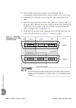
Install an additional LDF (Catalog Number 7244-9043100) or UDF (Catalog
Number 7244-9044100) panel as required.
10.
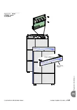
Install the rear cabinet nameplates at the top rear section of the cabinet. See
.

