Coral FlexiCom 6000 Installation Manual
Hardware Installation Procedure
2-23
Eq
uipment Insta
llation
2
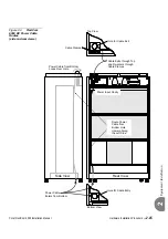
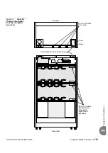
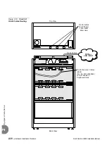
Figure 2-7
Coral I/O
Champ Cable Routes
from Top of Cabinet
(rear view)
I/O Cables from Top Enter Here
Rear View
Top View
J37
J41
J52
J50
J48
J44
J40
J46
J38
J42
J51
J49
J47
J45
J43
J39
J51
J49
J47
J43
J39
J45
J37
J41
J52
J50
J48
J44
J46
J38
J42
J40
Route I/O Cables
through Guide
Rings along
Right Side of
Backplane
Cover
RJ-45 I/O Cables
Enter Here
Screw


