background image


56 

3.1 Overall machine view   


To operate machine safely and properly, it’s crucial to fully understand the machine’s individual 
structure and operation methods for controlling equipments, as well as the presented meaning. 


1

bucket            2

bucket link      3

idler link        4

bucket cylinder   

5

arm                  6

arm cylinder    7

boom                          8

boom cylinder   

9

cab                  10

engine cover     11

counterweight   12

travel motor   

13

sprocket    14

carrier roller    15

track roller            16

idler roller   

17

track      


Summary of Contents for SWE150F

Page 1: ...Operation Maintenance Manual SWE150F SWE210F HYDRAULIC EXCAVATOR Sunward Intelligent Equipment Co Ltd 2015 07...

Page 2: ...this manual can not be engaged in any circumstances The excavator is designed according to the metric system all the data presented are metric and only metric parts and apparatus can be used The manua...

Page 3: ...t passenger 21 1 2 16 Worksite safety 22 1 2 17 Operation around loosened area 22 1 2 18 Signals and gestures from flagman 23 1 2 19 Distance to high voltage cables 23 1 2 20 Prevent scald 24 1 2 21 S...

Page 4: ...essure pipeline 41 1 4 8 Remove paint prior to welding or heating operation 41 1 4 9 Accessories 41 1 4 10 Maintenance precaution of track tension mechanism 42 1 4 11 Safety rules for high pressure oi...

Page 5: ...uction 97 3 3 8 Accumulator 104 3 4 Operation and control of the machine 105 3 4 1 Operator s position 105 3 4 2 Setting and adjustment 105 3 4 3 Work mode selection 106 3 4 4 Inspection before starti...

Page 6: ...6 4 3 2 Tightening torque table for hose 137 4 4 Maintenance schedule 138 4 4 1 Add lubricating grease 138 4 4 2 Engine oil 139 4 4 3 Gear oil 140 4 4 4 Hydraulic system 141 4 4 5 Fuel system 142 4 4...

Page 7: ...Circuit diagram 197 5 2 5 SWE210F Electric elements table 198 5 2 6 Hydraulic diagram 199 5 2 7 Hydraulic elements table 200 6 Accessories and option parts 201 6 1 Safety items 201 6 2 Attentions of...

Page 8: ...1 1 Safety rules Warning Please thoroughly read and completely understand all precautions described in this manual or safety labels Follow all instructions when operating or servicing this machine...

Page 9: ...ys keep them clean When cleaning them do not use solvents or gasoline It may cause labels to peel off There are also other labels in addition to warning labels Handle these labels in the same way In c...

Page 10: ...ust specify model of the machine when ordering Use only trained and qualified personnel to operate this machine Follow all safety precautions and instructions in this manual to keep your machine in go...

Page 11: ...tor sit over seat While switching the key to ON position except engine hour meter and LCD module all indicators of test system must light up Buzzer must sound as well Self test is finished in 2 second...

Page 12: ...rent ambient temperature Refer to stop engine section for properly parking machine and stopping engine Inspect fuel gauge on monitor top up is required Prevent dirt dust water and other foreign matter...

Page 13: ...the ground Run engine at low speed for 5 minutes Shut down engine remove the key Place pilot control lever to LOCK up position Open right side door to check oil level gauge Located on hydraulic oil ta...

Page 14: ...ise heat etc Check parts for looseness and lost Caution If any problems are detected repair prior to operation or contact our authorized distributor Use recommended fuel hydraulic oil and lubricant Us...

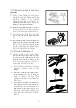
Page 15: ...in LOCK UP position Use wrench for filter to remove filter housing off the filter head cover by rotating counterclockwise Remove filter core and used 0 ring Clean the area in contact by head cover an...

Page 16: ...engine hood Be cautious of scalding after opening engine hood 9 Working device label Warning Stay clear of working device 10 Swing label Warning Keep clear of swing area 11 Rump label Warning Stay cl...

Page 17: ...l cool down There is pressure in existence in hydraulic oil tank Relieve pressure before opening cap to avoid oil spurt There is pressure which builds up in hydraulic piping Relieve pressure prior to...

Page 18: ...on as below e rotate upper carriage to left counterclockwise f rotate upper carriage to right clockwise g extend arm h retract arm Operation together with two pilot joysticks can also execute compound...

Page 19: ...12 18 No unauthorized access label Warning Stay clear of operation area of working device...

Page 20: ...son Always refilling fuel at outdoor Be sure to top engine before refilling fuel Do not refill fuel while smoking or near fire or sparks All fuel and most of lubricants are flammable Flammable liquid...

Page 21: ...exit mark to get out of the machine The safety structure being damaged is beyond repair But you could have it replaced with a new one Caution Pay attention to the flying pieces while breaking out eme...

Page 22: ...15 23 Gravity label 24 Hydraulic oil label 25 Greasing...

Page 23: ...odel and serial NO Learn about how to properly and safely operate machine and its controlling device Use only trained and qualified person to operate on this machine Keep machine at good working condi...

Page 24: ...ot avoided will result in death or serious injury WARNING indicates a potential hazard if not avoid it death or serious injury may incurred CAUTION indicates a potential hazard If not avoid may result...

Page 25: ...pital and fire brigade Take note of their telephone numbers for emergency contact 1 2 4 Protective articles Do not wear accessories or loose clothing Always wear close fitting clothing and protective...

Page 26: ...of entry into cab Remove all mud oil adhered to your shoes prior to access into cab Failure to do so your foot may slip and this may cause serious accidents Do not leave parts or tools around operator...

Page 27: ...ator s seat A comfortable posture can alleviate operator s fatigue You may adjust seat for your comfort in relation to your weight height and arm length Distance from hand lever for ideal hand operati...

Page 28: ...the work equipment to the ground set pilot safety control lever to LOCK position securely then stop the engine 1 2 14 Emergency exit way If the door can not be opened for some reason you may open the...

Page 29: ...e and condition of rock bed and take water depth flow speed into account prior to operation In the event of operation in vicinity of over bridge or overhead stuff be cautious not to collide with front...

Page 30: ...stood and follower by operators 1 2 19 Distance to high voltage cables Severe injury or death can occur to person due to any contact of any parts or load of machine with electric cables Always keep sa...

Page 31: ...driving parts to prevent hands feet hair and clothing being caught in machine 1 2 22 Prevent fire and explosion No smoke or using naked flame around fuel and engine oil Stop engine before refilling D...

Page 32: ...her person Machine must be fitted with falling object protective structure FOPS and front protective structure If machine is used in mining area or quarry where there is a risk of falling rocks 1 2 25...

Page 33: ...os disposal Do not allow other person to access working area 1 2 27 Cautious not to inhale exhaust gas If exhaust gas is inhaled this can cause diseases and even death If machine is operated at indoor...

Page 34: ...ed container Do not restore rags containing oil They may be ignited or self ignited Secure cap on refilling opening 1 2 30 Chemical disposal Serious injury can occur by allowing hazardous medical to m...

Page 35: ...tor s seat to a position where it is easy to carry out operation Check seat belt or mounting clamps for damage or wear Check meters to ensure they are functioning properly Check working lamp angle Mak...

Page 36: ...tart engine by short circuiting the engine including terminal starting this action is dangerous beyond dangerous it will cause damages to equipment 1 3 3 Start engine in cold weather Carry out a compl...

Page 37: ...lision with bucket can cause serious injury or death or damage to machine When using breakout hammer or other heavy working equipment there is a hazard of losing its balance and tipping over Do not lo...

Page 38: ...snow and can not be seen There is a hazard of the machine tipping over or hitting covered objects so always carry out operation carefully 1 3 7 Avoid tipping over Warning Do not attempt to jump off a...

Page 39: ...cesses to jobsite Sound horn or use other alarm to warn people When machine travels in reverse provide a flagman to assist in case operator s sight is limited Keep the flagman with operator s sight Wh...

Page 40: ...the pilot control switch When the machine is to park on a slope chock the machine on both side of the track lower bucket to dig the teeth into the ground Position the machine to avoid unexpected movem...

Page 41: ...to reduction switch is on engine revs may increase This may cause machine to speed up abruptly Avoid traveling on obstacles if possible if the machine has to travel on obstacles lower the working devi...

Page 42: ...to the front to improve the balance keep the working device 20 to 30cm and travel at low speed When traveling downhill lower the engine speed keep the travel lever close to the neutral position and t...

Page 43: ...e machine there is a hazard of tipping over or falling During transportation on road follow the local laws and regulations Study all local laws or regulations concerning limiting load weight width and...

Page 44: ...er to LOCK position and then stop the machine To prevent unauthorized person from operating the machine always close the cab door use the key to lock all the equipment Then remove the key and keep the...

Page 45: ...ance or service Set the other warning signs around the machine if necessary 1 4 2 Parking the machine prior to service Park the machine on firm level ground Lower the bucket to the ground Switch off t...

Page 46: ...to support the machine and working device securely Dispose of replaced parts in time remove any accumulated lubricating grease oil or debris Always disconnect negative terminal from battery before te...

Page 47: ...rounding people 1 4 5 Welding and grinding precautions Welding operation can generate flame and gas Operate must be therefore carried out in well ventilating area with complete preparation Store flamm...

Page 48: ...out painting operation outdoor or in ventilating area Dispose of paint solvent properly Remove paints prior to welding or heating operation When using grinder or sand paper to remove paints always we...

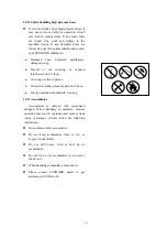
Page 49: ...ury and even death Do not disassembly recoil springs 1 4 11 Safety rules for high pressure oil Hydraulic system is always under internal pressure When inspecting or replacing piping or hoses always ch...

Page 50: ...wire layer Covering swollen in places Twisted or crushed movable portion of hose Foreign material embedded in covering 1 4 13 Accumulator Accumulator is charged with pressurized nitrogen When handling...

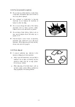
Page 51: ...n battery failure to do so may cause explosion Heat the battery up to approx 16 C The electrolyte is toxic In case of explosion electrolyte may splash into eyes and cause blindness When inspecting ele...

Page 52: ...45 2 Transportation and storage Warning Before reading this chapter please thoroughly read and fully understand the contents described in chapter SAFETY RULES in this manual...

Page 53: ...elect proper transportation tools according to machine s weight length width and height Survey the traffic condition for transportation in advance e g road condition and width height of bridges and tu...

Page 54: ...emely dangerous The machine is subject to rolling over If the machine needs to change direction go back to level ground or trailer platform then revise travel direction and cross the slope Do not atte...

Page 55: ...vice at the front of the machine and travel forward If no working device travel in reverse to load the machine Align the direction of the machine with the ramp be sure the center line of the machine t...

Page 56: ...lower the boom place an wooden block under bucket cylinder to prevent damages to it during transportation Pull the pilot safety lever to LOCK position stop the engine remove engine starting key and lo...

Page 57: ...r fully warm up the machine Unloading procedure Switch off idle speed function set travel speed to low speed position adjust engine throttle knob to set engine speed at low speed Raise boom to proper...

Page 58: ...he sprocket end set the undercarriage and upper structure parallel Do not swing to the other direction Do not lift the machine in any posture other than the posture given in the right fig When lifting...

Page 59: ...support rod with sufficient length to keep them not to hit machine during lifting operation Cover steel rope or rod with protective material to avoid damages to machine if necessary Put steel ropes th...

Page 60: ...s out Change engine oil Apply grease to exposed parts on piston rod Top up fuel tank with diesel oil Disconnect battery negative terminal and secure battery cover You can also remove the battery from...

Page 61: ...el and lubrication status Air condition must run once a month 2 2 3 After storage Note Start engine only in well ventilated condition Remove lubricating grease on piston rod surface Apply grease to al...

Page 62: ...55 3 Operation Warning Before reading this chapter please thoroughly read and fully understand the contents described in chapter SAFETY RULES in this manual...

Page 63: ...dual structure and operation methods for controlling equipments as well as the presented meaning 1 bucket 2 bucket link 3 idler link 4 bucket cylinder 5 arm 6 arm cylinder 7 boom 8 boom cylinder 9 cab...

Page 64: ...lot safety control lever 2 start switch 9 left pilot control handle with manual idle switch 3 work light switch 10 right pilot control handle with horn switch 4 wiper switch 11 travel control lever 5...

Page 65: ...cification of these control levers is shown in fig When operating the safety lock lever upward or downward pay attention not to touch the other control levers Pilot safety lock lever is a device being...

Page 66: ...achine is traveling sudden steering can cause damage to machine Travel control lever 2 is being used to control machine s travel a forward Push lever forward pedal forward tilting b reverse Pull lever...

Page 67: ...panel 1 close button 2 wind speed switch 3 temperature setting switch 4 air outlet mode setting switch 5 auto mode setting switch 6 inner exterior air in switch 7 liquid crystal display screen 8 air...

Page 68: ...andard mode H is heavy load mode 4 Press F4 travel speed is switched between high speed and low speed icon of travel low speed is icon of travel high speed is 5 Press F5 work state is switched between...

Page 69: ...information it will display this information when GPS lock the machine it has 5 states or it will not display this cue information 12 System time 2015 5 19 10 40 means May 19 2015 twenty to eleven 13...

Page 70: ...is less than 1200 r and engine water temperature is less than 25 the machine will enter into warming status the icon is flash in the process of warming Press the idle speed switch it will display mean...

Page 71: ...tering into hand regeneration system will return to the main interface If operator press F5 system will return to main interface but if engine still have the requirement of hand regeneration system wi...

Page 72: ...t fuel filter element and air filter element If there are no need to maintenance please press F1 2 After replaced engine oil filter element press F5 set maintenance time again 3 After replaced diesel...

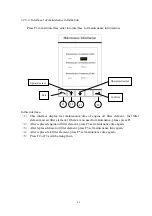
Page 73: ...In this interface 1 This interface is used to confirm for re setting maintenance time of engine oil filter element fuel filter element and air filter element 2 Press F5 is confirming for choice 3 Pres...

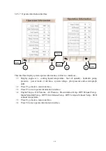
Page 74: ...mation warning and failure information user setting system setting machine information history failure record throttle calibration loading technology 2 Blue item is the current item 3 Press F1 is exit...

Page 75: ...em voltage pilot pressure and accelerograph shift 2 Press F1 go back to menu interface 3 Press F5 to next operate information interface 4 Engine Torque Oil Pressure Air Pressure Pressurization Temp DP...

Page 76: ...his interface display system port information in this interface 1 Included 3 interfaces it has simulate signal and digital signal 2 Press F4 and F5 switch among 3 interfaces 3 Press F1 go back to syst...

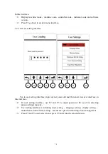
Page 77: ...ssword and then enter into user interface in this interface 1 In user setting interface use F2 and F3 to input password F4 used for selecting password digit capacity 2 User setting interface is includ...

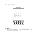
Page 78: ...3 2 5 10 1 Clock setting interface In this interface 1 F4 is used to select amended parameter F2 and F3 used to amend parameter F5 is used for conforming the amended value press F1 is exit F1 F2 F3 F4...

Page 79: ...72 3 2 5 10 2 Language setting interface In this interface 1 Press F2 and F3 used to select language F5 is confirming F1 is exit F1 F2 F3 F5...

Page 80: ...73 3 2 5 10 3 Screen luminance setting interface In this interface 1 Press F2 and F3 used to adjust luminance F5 is confirming F1 is exit F1 F2 F3 F5...

Page 81: ...3 2 5 10 4 Screen luminance setting interface In this interface 1 Press F2 and F3 used to adjust interval time F4 is used to select project which is need adjust F5 is confirming F1 is exit F1 F2 F3 F5...

Page 82: ...nterface In this interface 1 Press F2 and F3 used to amend password F4 is used to select needed password digit capacity F5 is confirming F1 is exit When input correct password then you can set new pas...

Page 83: ...ssword amend interface In this interface 1 F2 and F3 used to begin to time or time reset when select begin to time lease hour triggered when select time reset lease hour reset press F5 confirm press F...

Page 84: ...corresponding information of failure or warning code 2 Interfaces can be switched by F4 3 F1 is exit In this interface 4 You can consult corresponding information of engine failure or warning code 5 I...

Page 85: ...ord interface History failure record interface 4 1 History failure record interface 4 2 History failure record interface 4 3 History failure record interface 4 4 In this interface F1 F2 F5 F3 F4 F1 F2...

Page 86: ...abnormal system so please try your best to contact with Sunward or the person who is authorized by Sunward to deal with it In this interface 1 First enter into password input interface F4 select amen...

Page 87: ...brating please just after system is normal motor calibration state will cue you it has calibrated 6 Press F1 go back 3 2 5 14 Loading counter interface In this interface 1 Start cancel loading counter...

Page 88: ...ple push joystick towards right front boom down and bucket dumping proceed at the same time 3 2 7 Horn switch Horn switch 97 is used to control hydraulic excavator work horn This horn switch is locate...

Page 89: ...g b arm digging c right slewing d left slewing N neutral the upper structure and the arm stay where they are and remain immovable 3 2 9 Automatic slow down switch The automatic slow down switch can sl...

Page 90: ...ngine starting position When starting the engine hold the key in this position With engine started release the key immediately it will go back to ON position automatically Note Some starting switch ON...

Page 91: ...ight work light monitor light will be cut down Light will be shut down 3 2 13 Wiper switch Wiper switch is used to control wiper located on front window of the cab Set the wiper switch to ON position...

Page 92: ...eset to OFF 3 2 16 DPD Regeneration Lamp Regeneration indicator lamp indicates whether the engine into the ongoing regeneration And what is the regeneration process Green indicator lamp is flash means...

Page 93: ...t will immediately stop running or it will not be able to start When switch at ON position the engine can be normally start and stop 3 2 18 Memory Clear Switch Record clear switch is used to clear the...

Page 94: ...dow or door Warning Serious accidents may occur if fail to lock the control lever and touch it unexpectedly Check if the wiper blades are in fixed position Use both hands to grip handle A firmly press...

Page 95: ...r movement then grip the handle B and push it upward to open the canopy To close it grip handle B and use lock button A to lock canopy automatically refer to right fig Inner lock Push ball handle A fo...

Page 96: ...door frame the fixed lock will be open as fig 3 then close the cab door Emergency exit When the cab door can not open due to some reasons safety hummer can be used to broken the back window you can es...

Page 97: ...oor or covers with lock Insert the key into the key slot turn the key counter clockwise and pull the handle to open the door or covers Turn the key clockwise to lock the door or covers see the right f...

Page 98: ...e lock is open To lock the fuel filling opening turn the B clockwise Rotate oil fill cap B counter clockwise to open oil fill port To lock up oil fill port rotate B clockwise see fig below Hydraulic o...

Page 99: ...ition 15 Uses can select different frequency channel for listening according to your needs and likes as a way to alleviate your fatigue power control key AM FM auto tuning brief listening to station p...

Page 100: ...seconds The current frequency being listened will be restored in corresponding place 6 stations for each band 30 stations total Auto tuning and restore radio station the key AS PS is pressed for longe...

Page 101: ...t will automatically return to clock adjustment mode if there is no operation for 5 seconds Precautions Set volume in proper position to prevent traffic accident In case of hot or cold weather please...

Page 102: ...er 3 turn the backrest or the backrest will turn forward automatically Adjust the backrest to the optimal position and convenient for operation then loose the lever C Seat height adjustment Lift the s...

Page 103: ...switch prior to fuse replacement The fuses protect the electrical equipment and wiring from burning out Replace any fuse with corrosion or generating white powder or any fuse looseness in fuse holder...

Page 104: ...gs are provided in this manual If you fail to pay attention to these information you or the other persons may suffer the injury and even death Schematic diagram This air conditioning is heat refrigera...

Page 105: ...ed the lamp above the switches will be lighted The function of buttons and switches are as follows Close button 1 start and close control of fan and air conditioner Press the OFF switch 1 the display...

Page 106: ...the air outlet mode Press button 4 mode switch will be displayed on the screen Air will be sent out by the outlet mode displayed on the screen Air outlet mode will switched automatically when auto mod...

Page 107: ...arts Under the auto mode inner air circulation mode and exterior air leading in mode switches automatically Liquid crystal display screen 7 Display the setting temperature input air air outlet situati...

Page 108: ...ear that refrigeration effect is influenced For engine cooling water is used by heating system when environmental temperature is low and the machine runs for a while then engine water temperature reac...

Page 109: ...ess switch 2 to adjust input air and confirm the temperature and input air through display screen 2 Press switch 4 to choose air outlet mode will display on the screen 3 Make sure that switch 8 is on...

Page 110: ...3 seconds then fault code will displayed on the screen Setting temperature This function is used for switch between centigrade degree and Fahrenheit degree Press temperature setting switch and at the...

Page 111: ...bleed the air Please contact distributor The accumulator is fixed in control piping The accumulator is a device being used to store pressure With this accumulator equipped you are allowed to operate...

Page 112: ...io and air conditioning 3 4 2 Setting and adjustment The machine has the following settings Engine rev setting Turn the throttle knob to get desired revs Work mode setting S H L For detailed informati...

Page 113: ...g operation following a sequence as S L H S S medium load work mode L light load work mode H heavy load work mode It s a complete shift cycle The applicable work conditions corresponding to individual...

Page 114: ...out piping leakage etc If any abnormal signs are detected please clear them Check work equipments cylinder link hose free of crack wear out or and variation Check engine oil level the level must be be...

Page 115: ...ition before starting the engine Do not keep the starting motor running continuously for longer than 5 seconds If the engine fails to start wait 2 minutes before a new attempt Start the engine in norm...

Page 116: ...ngine Do not keep the starting motor rotating continuously longer than 5 seconds If it fails to start wait 2 minutes before another attempt With engine started release the key it will return to ON pos...

Page 117: ...ct and service life Please follow the rules specified in this manual After starting the engine do not attempt any operation allow it to idle for 15 seconds After idle running attempt all digging swing...

Page 118: ...ottle knob to set engine revs to 1500 rpm operate bucket to perform dig dump blank action for 5 minutes without attempting any other actions Engage engine speed at 1500 rpm operate bucket and arm to a...

Page 119: ...to warn people before traveling Do not operate machine unless you are seated in position Do not take other personnel Make sure door windows are in lock up position and locked securely Do not travel i...

Page 120: ...peed at LOW position Never change direction on slopes or attempt upper structure swing operation When passing under bridge tunnel or other place with limited height check to make sure the machine coul...

Page 121: ...control lever or pedal in sync the machine will move forward pull backward both travel control lever or pedal in sync the machine will move in reverse The machine present 2 travel speed stage high lo...

Page 122: ...ravel right push right travel lever or pedal to travel left When idle roller is located under cab pull left travel lever or pedal backward to travel left Pull right travel lever or pedal backward to t...

Page 123: ...116 When the sprocket is located under cab the relationship between operation direction and machine travel direction is in reverse of item above...

Page 124: ...ing When the machine is set to auto idle state the machine will stop all action for 10 seconds and then engine will go to idle speed state automatically Since then any operation on lever will shift th...

Page 125: ...e with bucket link the max digging force of arm and bucket can be achieved The range for excavating with the arm is from a 45 away from the machine to a 30 angle toward the machine Machine can execute...

Page 126: ...ucket teeth in level When arm is near the inner side of excavator and at right angle to the ground lower the boom and fold the bucket at the same time to move the bucket teeth in level Loading work Th...

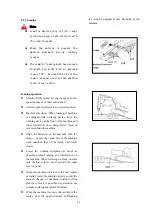
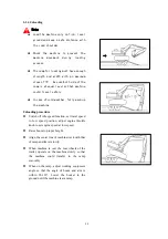
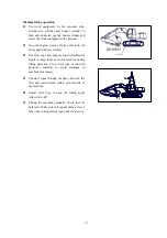
Page 127: ...that the chassis rises approx 5 cm 2 in off the ground Do not let the machine come further off the ground than this amount Always keep the chisel pressed against the impact surface properly to preven...

Page 128: ...he end of strokes Do not operate using the swing force Do not move the chisel while carrying out impacting operations Do not move chisel to gather in pieces of rock Do not holding the chisel horizonta...

Page 129: ...it has penetrated the rock Do not move work equipments to drive breaker to work When folding arm and breaker do not impact boom let alone step down impacting pedal to cause chisel to hit boom This ca...

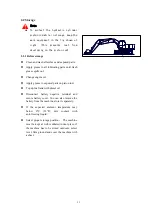
Page 130: ...ote Do not operate too quickly failure to do so may cause boom s sudden up movement and lead to accidents Do not operate any other lever and actions failure to do so boom can not be lowered due to pre...

Page 131: ...on all action of the machine will stop However the machine will act when operating control valve 2 Set pilot safety lever to LOCK position the machine will stop In this case the machine will not be st...

Page 132: ...rocess of automatic regeneration This does not indicate a failure Also it is not required to operate the DPD switch When the engine is stopped during automatic regeneration the regeneration operation...

Page 133: ...ly lasts for 15 to 20 minutes but the last time mainly depend on the external environment temperature 5 At the end engine rev speed recover to idle speed orange lights out manual regeneration finished...

Page 134: ...e the ground under the machine may collapse and cause the machine to fall 3 To make it easer to escape if there is a problem set the tracks at right angle to the road shoulder or cliff with travel mot...

Page 135: ...work equipments 6 When carrying out demolition work do not carry demolition above your head there is hazard of broken parts falling off 7 When using breaker or other heavy duty equipments do not lowe...

Page 136: ...129 4 Maintenance and service Warning Before reading this chapter please thoroughly read and fully understand the contents described in chapter SAFETY RULES in this manual...

Page 137: ...genuine parts your warranty rights will become void Do not adjust engine speed limiter or hydraulic system safety valve Do not allow water to reach electric equipments Do not dismantle engine pump con...

Page 138: ...le function Allow engine to idle for 5 minutes Set the key to OFF position Set safety lock lever to LOCK position Post DO NOT OPERATE to the machine 4 1 5 Handle fuel and lubricant properly Important...

Page 139: ...etail information about the checks when operating engine Please maintenant it with two people If the inspection and maintenance items work properly Is there any leakage of fuel or oil when engine spee...

Page 140: ...coolant and filter 4 2 1 Lubricant and hydraulic oil Oil is used in the engine and hydraulic equipment under extremely severe conditions high temperature high pressure and deteriorates with the use A...

Page 141: ...ant wait for the engine to cool down If the coolant level is low it will cause overheating and will also cause problems with corrosion from the air in the coolant 4 2 4 Grease Grease is used to preven...

Page 142: ...ngine oil pan Engine oil SAE 30 SAE 10W SAE 10W 40 SAE 15W 40 SAE 5W 30 Swing reductor SAE 30 Travel reductor Hydraulic system SAE 10W SAE 10W 30 SAE 15W 40 Fuel tank Diesel oil ASTM D975 No 2 GB252 p...

Page 143: ...10 17 66 6 7 48 5 59 74 6 0 7 5 43 4 54 2 12 19 11 11 5 83 2 98 123 10 0 12 5 72 3 90 4 14 22 177 18 130 2 157 196 16 0 20 0 115 7 144 7 16 24 279 28 5 206 1 245 309 25 0 31 5 180 8 227 8 18 27 382 39...

Page 144: ...value Permissible range N m kgf m lbft N m kgf m lbft 9 16 18UNF 19 44 4 5 32 5 35 63 3 5 6 5 25 3 47 0 11 16 16UN 22 74 7 5 54 2 54 93 5 5 9 5 39 8 68 7 13 16 16UN 27 103 10 5 75 9 84 132 8 5 13 5 61...

Page 145: ...on both side of cylinder 8 Individual pin roll of arm and bucket 8 Swing bearing all track 2 Swing mechanism grease chamber 1 bucket arm and boom rotary gear swing bearing etc 20 to 40 C 4 to104F BP B...

Page 146: ...y 500 hours For the other aspects please carry out the maintenance procedure following the requirements specified in diesel engine manual The performance difference among different engine oil is big W...

Page 147: ...y 250 hours refill if necessary Note Filling quantity of gear oil should be defined by the height of oil pointer Recommended gear oil name Gear oil supplier Gear oil 20 to 40 Esso Esso Gear Oil GP80 9...

Page 148: ...piping Leakage Crack and twist Note Hydraulic oil replacement interval is relating to its type with different type of engine oil the replacement interval varies Recommended hydraulic oil brand name Oi...

Page 149: ...e interval from every 500 hours to every 250 hours depending on the fuel management and refuel staus 4 4 6 Intake Exhaust System Inspection Maintenance Item Daily 250 500 750 1000 1250 1500 Remarks Re...

Page 150: ...eplace cooling water once a year or every 2000 hours whichever comes first in the event of using SUNWARD genuine long life coolant 3 If the machine works at dust area shorten maintenance interval 4 4...

Page 151: ...144 4 4 9 Hose...

Page 152: ...ter core 1 Every 500 hydraulic oil filter core 730403000186 oil return filter core 1 Every 1000 pilot filter 730403000106 pilot filter core 1 Every 1000 air filter 750201012270 air outer filter core 1...

Page 153: ...radiator and oil cooling fins to remove embedded dust and dirt Clean up fuel suction cartridge and filter more frequently Clean up frequently especially the surface of alternator and starter rectifier...

Page 154: ...boom cylinder foot 2 places 2 boom foot pin 2 places 3 boom cylinder rod end 2 places 4 arm cylinder foot pin 1 place 5 boom arm connecting pin 2 places 6 arm cylinder rod end 1 place 7 bucket cylind...

Page 155: ...e and secure port cover Note The oil level checking operation should be carried out 10 minutes after shut down If checking oil level the moment machine has just been shut down incorrect number will be...

Page 156: ...position stop the engine and remove the key from starting lock Set pilot safety lock lever to LOCK position Open inspection door right back door for main pump check fluid level to ensure that hydrauli...

Page 157: ...m starting lock Set pilot safety lock lever to LOCK position Loosen drain valve underneath diesel oil tank to drain water and deposit Collect them with container Fasten valve the moment clean diesel o...

Page 158: ...starting lock set pilot safety lock lever to LOCK position Check hose for any twist abrasion check hose clamp for looseness or lost Check damages of cooler Check flange for looseness and oil leakage W...

Page 159: ...f engine oil pan Open drain valve to drain engine oil Note The engine oil might be hot be care to handle it without being burned 5 With engine oil drained fasten and secure drain valve Replace engine...

Page 160: ...ick is reached Engine oil capacity 25L 12 Cap oil filling port 13 Start engine run it unloaded at low speed for 5 minutes Check engine oil pressure indicator red on monitor to make sure it goes off If...

Page 161: ...rain the oil to ground ditch river pond or lake Dispose of waste oil properly After work engine temperature is still high After replacing the oil filter wait for the engine to cools down Keep flame or...

Page 162: ...g surface of filter bracket Then fasten 1 2 more turns Fastening too much may cause damages to contact surface and leading to signs of oil leakage If fastening too loose fuel may leak from contact sur...

Page 163: ...5 minutes Stop the engine remove key and set pilot control lever to LOCK position 4 Clean up upper hydraulic oil tank to prevent dirt getting into hydraulic system Press lock cap to release internal...

Page 164: ...tes then stop the engine remove key set pilot control lever to LOCK position Clean up upper hydraulic oil tank to prevent dirt getting into hydraulic system press down lock cap to release internal pre...

Page 165: ...ey to check fan belt tension 12 The deflection A should be 8 12mm when the pressing with a pressure of 10kgf 98N 13 If the tension is not within specific range loosen bolts on adjust plate and engine...

Page 166: ...remove air filter end cover Remove outside filter 2 clap slightly with hand Never hit it with hard stuff Note Minimize pressure of compressed air 0 2 MPa 2kgf cm 2 let go of personnel around to avoid...

Page 167: ...or Loosen the mounting bots located on left side of condenser open up condenser of A C Use compressed air below 0 2 MPa or water to rinse condenser Remove the strainer if present in front of radiator...

Page 168: ...then check to make sure that nuts contact with track link surfaces securely 2 After checking retighten 120 10 Rubber block if mounted 1 Tighten at torque 549 59 N m 56 6 kgf m 405 43 lbft 2 After tigh...

Page 169: ...in If the track tension is not at standard value adjust it in the following manner 1 Pump in grease through grease fitting 2 with a grease pump pump fitting 2 and plug screw 1 are integral 2 To check...

Page 170: ...ine to idle at high speed and operating air conditioning to extra refrigerating state there must be small amount of bubbles in inspection glasses which is fixed on condenser reservoir There are bubble...

Page 171: ...ccording to the ambient temperature So dilute the washer fluid with water following the table below Note Pure detergent are divided into 2 categories 10 C 14 F general use and 30 C 22 F cold area use...

Page 172: ...at one place the measurement is a little bit easy The position shown in fig is left position It s easy to measure correctly if using pin gauge Loosen 4 fixed bolt 2 and plate 3 Remove shim 4 accordin...

Page 173: ...in the surrounding area During replacement operation there is hazard of flying out pieces So wear protective glasses gloves and other protective equipment Lower the bottom surface of the bucket on a...

Page 174: ...service at the same time 4 5 6 1 Checking swing redactor gear oil level Stop the machine at level ground Shut auto idling switch to run the engine unloaded at low temperature for 5 minutes Important...

Page 175: ...work gear temperature may be very high Wait for temperature to cool down before loosening oil fill plug of fill port 1 Pay attention that to keep body and face away from oil fill port 1 during operati...

Page 176: ...kgf Adjust Loosen bolts 1 Pull adjusting screw blot 2 make deflection of belt to be 5 8 mm about 58 8N 6 kgf Fasten bolts 1 Check if belt pulley is broken and if V groove and V belt are wearing Especi...

Page 177: ...ressure of compressed air 0 2 MPa 2kgf cm 2 let go of personnel around to avoid scattered broken pieces wear personal protective articles including goggles and protective glassed Use compressed air to...

Page 178: ...un the engine unloaded at low speed for 5 minutes Important Stopping the engine improperly may damage turbocharger Set start key to OFF position stop the engine remove the key from starting lock set s...

Page 179: ...Then remove grease fill port cover 1 Check that grease height in the position where pinion passes by should be at least 14mm 0 6in and free of pollution add 0 5kg lubricate grease to reach standard he...

Page 180: ...lock set safety lock lever to LOCK position Note After completing work the gear oil temperature might be very high wait for temperature to cool down Place a container under drain pipe to collect oil L...

Page 181: ...Wait for the temperature to cool down before gradually loosen the plug of oil fill port 1 Keep face and body away from plug of oil fill port during the process of work With the oil cooled down gradua...

Page 182: ...stop the engine remove key set pilot control lever to LOCK position Clean up upper hydraulic oil tank to prevent dirt getting into hydraulic system press down lock cap to release internal pressure Cl...

Page 183: ...ss swing upper turret 90 degree then stop the machine at level ground Position excavator with arm cylinder fully retracted and bucket cylinder fully extended Lower bucket to ground run engine unloaded...

Page 184: ...hen using hydraulic breaker the maintenance and replacement interval should be shortened by half Swing upper structure by 90 degree stop the machine at firm level ground Clean upper hydraulic oil tank...

Page 185: ...r from fuel system Drain out the off grade fuel Fill with proper fuel Check starting circuit clear the problem Charging or replace new battery Clean filter or replace new filter Clean up filter or rep...

Page 186: ...or loosened Defective belt pulley Defective cooling system Defective temperature sensor Ejection oil pump unpunctual Separator sponge peel off Add coolant Drain out then replace with specified coolant...

Page 187: ...ing Ejection oil pump unpunctual Ejection nozzle gets polluted Defective engine main block engine main body malfunction Draining out and replace with proper fuel Check intake system replace clean up i...

Page 188: ...lubricate piping Remove exhaust pipe and air intake hose for inspection Contact your designated distributor Check piping and repair Contact your designated distributor Turbocharger joint leakage Beari...

Page 189: ...repair Contact your designated distributor All indicators do not work Fuse blown out Defective wiring circuit Defective circuit board Replace fuse Check circuit and repair or Contact your designated...

Page 190: ...distributor Contact your designated distributor Contact your designated distributor High low travel speed selection does not work Travel pilot pressure switch Defective controller Defective solenoid...

Page 191: ...se proper hydraulic oil Add hydraulic oil to reach specified scale level Filter or drain out and refill with proper oil Clean radiator and front drainer Clean or replace filter Contact distributor Con...

Page 192: ...Insufficient lubrication of idle roller or track roller Get stuck by stones Defective brake Defective pilot valve adjust lubricate remove and clear repair replace or contact our distributor repair rep...

Page 193: ...186 5 Technical specification...

Page 194: ...999 L Rated power revs 95kW 2200rpm Max torque revs 420N m 1800rpm Fuel tank capacity 245 L Fuel capacity Main pump 2 axial piston pump Flow capacity 2x139L min Work pressure setting 31 4 34 3 26 MPa...

Page 195: ...Track total length 3740 C Platform distance to ground 920 D Platform slewing radius 2350 E Upper structure width 2450 F Track gage 2000 G Chassis width 2600 H Track width 600 I Chassis distance to gr...

Page 196: ...ation SWE150F A Max digging height 8630 B Max dumping height 6130 C Max digging depth 5640 D 8 feet level digging depth 5440 E Max vertical digging depth 4540 F Max digging radius 8355 G Max reach at...

Page 197: ...190 5 1 4 Circuit diagram...

Page 198: ...atmospheric pressure sensor 30 quick change locked switch 10 main relay 31 pressure selection switch 11 parking motor relay 32 wane switch cover plate 12 preheat relay 33 DPD manual regeneration wane...

Page 199: ...192 5 1 6 Hydraulic diagram...

Page 200: ...in pump 1 3 Swing motor 1 4 Right travel motor 1 5 Left travel motor 1 6 Central swing joint 1 7 Left pilot joystick 1 8 Right pilot joystick 1 9 Double pedal valve 1 10 Pilot filter 1 11 Low pressure...

Page 201: ...re stoke 115mm 125mm Displacement 5 193 L Rated power revs 128 kW 2000rpm Max torque revs 677Nm 1500rpm Fuel tank capacity 370 L Main pump 2 axial piston pump Flow capacity 2x234L min Work pressure se...

Page 202: ...Track total length 4450 C Platform distance to ground 1060 D Platform slewing radius 2750 E Upper structure width 2710 F Track gage 2200 G Chassis width 2800 H Track width 600 I Chassis distance to g...

Page 203: ...chine specification SWE210F A Max digging height 9740 B Max dumping height 6980 C Max digging depth 6690 D 8 feet level digging depth 6500 E Max vertical digging depth 6040 F Max digging radius 9950 G...

Page 204: ...197 5 2 4 SWE210F Circuit diagram...

Page 205: ...ensor 31 quick change locked switch 10 main relay 32 pressure selection switch 11 parking motor relay 33 wane switch cover plate 12 preheat relay 34 DPD manual regeneration wane switch 13 start motor...

Page 206: ...199 5 2 6 Hydraulic diagram...

Page 207: ...in pump 1 3 Swing motor 1 4 Right travel motor 1 5 Left travel motor 1 6 Central swing joint 1 7 Left pilot joystick 1 8 Right pilot joystick 1 9 Double pedal valve 1 10 Pilot filter 1 11 Low pressure...

Page 208: ...leaked lubricating oil and grease Appoint one person conduct operating and obey him when the machine is lifting When install or demount operation device Make sure the machine stop stability and avoid...

Page 209: ...ment work range will suddenly become larger so it has the dangerous of corrosion objects and misjudged distance When operate work attachment please keep distance to any object in the area 6 3 Hydrauli...

Page 210: ...open the cut off valve Before dismantling and installation pipe please close stop valve to prevent the hydraulic oil flow out 6 3 3 Control hydraulic quartering hammer Break is controlled by left foo...

Page 211: ...204 Tread pedal hydraulic breaker hamm er begin to work Picture 1 Prohibit put foot on the pedal when it is not operated to prevent misoperation...

Page 212: ...to the mechanical load when rod position is incorrect or when used it as a lever occurs runaway Percussio n sounds will change when runaway c Forbid to push rock Forbid using side wall of quartering...

Page 213: ...s will have mud and make quartering hammer be damaged beforehand I Do not operate quartering hammer in the water or mud When parts except drill shank sink in the water or mud please stop operating qua...

Page 214: ...ydraulic quartering hydraulic oil will go bad quicker than daily excavate so it must frequently replace hydraulic oil and core if replace hydraulic oil and core do not on time it will damage machine a...

Page 215: ...arm 2500mm Lengthen arm 1 2800mm Lengthen arm 2 3100mm Bucket Rated bucket capacity Cutting width Standard bucket 0 6m 900 option SWE210F Option list Arm Arm length Standard arm 2920mm Bucket rated b...

Page 216: ...Add 16 LiXiang Road Xingsha economic and technologic development district Changsha Hunan Tel 0086 0731 83572660 83572828 Maintenance point Our office in various provinces and cities of China Distribu...

Reviews: