background image


Sunrise Internet Box User Manual


Page 131


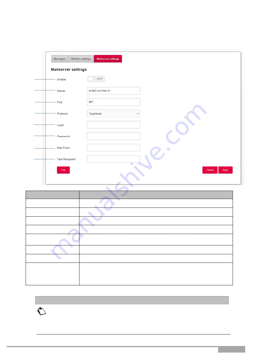
3.10.1.3 Mail server settings 


Objective: 

This menu is used to set up the email address to which notifications will be sent in case 
of receipt of voice mail messages. 


Field


Meaning/Action


1. 

Enable 

Select if you want the feature to be on/off 

2. 

Server 

Enter the SMTP server to address here. 

3. 

Port 

Select the port to address. 

4. 

Protocol 

Select the protocol you want to use (SSL / SMTP / Cyphered) 

5. 

Login 

Enter the email address of the account from which you want to send 
the recorded voice messages. 

6. 

Password 

Enter the corresponding password for the e-mail account used 

7. 

Mail from 

Please enter the e-mail address of point 5 again in this field. 

8. 

Test Recipient 

Enter the e-mail address to which the test mail should be sent. 

Note:

 Once sent, this e-mail may end up in the SPAM folder of your 

mail program. Please double check this folder in case it is not received 
in your inbox. 


You must enter your email address in the 

Mailbox settings

 menu. Valid 

characters are:  
A-Z a-z 0-9 and .!#$%&'*+-/=?^_`{|}~ 


Note


Summary of Contents for Internet Box

Page 1: ......

Page 2: ...pose of this user manual is to provide users with information on the functions for operating and managing the equipment The access level Administrator presented is protected by a password and allows access to all these functions in read and write mode for all network parameters Configuration of the Sunrise Internet Box by the web interface is described in detail see Section 3 This user manual desc...

Page 3: ...ion 1 Presentation of Sunrise Internet Box equipment Section 2 Description of Sunrise Internet Box equipment Section 3 Configuration of the Sunrise Internet Box by HTTP Section 4 Description of Internet access service Section 5 Fiber mode Annex A Troubleshooting Annex B EC compliance declaration Annex C Environment Annex D Technical features Annex E Glossary Annex F Connector technology ...

Page 4: ...ur phone 18 2 4 3 Powering up 19 2 4 4 Connecting a Set Top Box STB to your Sunrise Internet Box 20 2 5 Default configuration 21 2 5 1 Default password 21 2 5 2 Default configuration for the local network LAN 22 2 5 3 Default configuration for the local wireless network WLAN 22 3 Information Configuration 23 3 1 Accessing the welcome screen 23 3 2 Recommendations 26 3 3 Device configuration 27 3 3...

Page 5: ...stics 98 3 7 6 Mac Filter 99 3 7 7 Wi Fi Scheduling 100 3 7 8 Wireless Environment 102 3 8 Voice service 103 3 8 1 Voice settings 103 3 8 2 Line settings 108 3 8 3 DECT settings 109 3 8 4 DECT Setup 112 3 8 5 DECT Handset settings 116 3 8 6 Calling operations 117 3 8 7 DECT Scheduling 119 3 8 8 DECT Eco Mode 120 3 8 9 Busy on Busy 121 3 9 USB service 122 3 9 1 USB device 122 3 9 2 Printer sharing ...

Page 6: ...Page 6 Sunrise Internet Box User Manual Annex B Safety warnings 154 Annex C Environment 155 Annex D Technical features 156 Annex E Glossary 161 Annex F Connector Technology 164 ...

Page 7: ... ADSL VDSL line telephone set Power Supply Connection Total local loop unbundling 18 Figure 2 4 ADSL VDSL line telephone set Power Supply Connection Partial local loop unbundling 19 Figure 2 5 Set Top Box connection in Routed mode 20 Figure 3 1 xDSL line telephone set Power Supply Connection Total local loop unbundling 112 Figure 3 2 xDSL line telephone set Power Supply Connection Partial local lo...

Page 8: ...aneous access to Triple Play services The Sunrise Internet Box product adapts ADSL and VDSL functions for POTS Using these interfaces this gateway enables you both to surf the Internet and watch television It also lets you make phone calls over the Internet from a classical analog telephone set or an IP SIP telephone The Sunrise Internet Box has two Phone ports The Sunrise Internet Box is also equ...

Page 9: ...Sunrise Internet Box User Manual Page 9 Figure 1 1 Home Network Overview ...

Page 10: ...nect your Sunrise Internet Box to your telephone line 3 1 Ethernet RJ45 RJ45 cable used to connect your Sunrise Internet Box to the Ethernet port of your computer 4 Mains adapter 5 Quick start guide 6 2 Reichle connector adaptors 7 SFP module Optional accessory Incomplete or damaged supply If upon receipt the equipment is damaged or incomplete please open an Internet browser and go to www sunrise ...

Page 11: ...es a minimum of Internet access xDSL or Fiber a power socket a computer equipped with a Wi Fi 802 11n or 802 11ac interface or an Ethernet interface 10BASE T or 10 100BASE T or 10 100 1000BASE T Optimized desktop resolution 1200x800 a WEB browser Firefox Chrome Microsoft Edge Tablet Android IOS Smartphone ...

Page 12: ...ernet Box User Manual 2 Description and hardware installation of the Sunrise Internet Box 2 1 Description The following figure gives an overview of the Sunrise Internet Box Figure 2 1 Overview of the Sunrise Internet Box ...

Page 13: ...unrise Internet Box Long press more than 10s resets the Sunrise Internet Box to the factory configuration Note The long press deletes the entire personalized configuration of your Sunrise Internet Box password configuration etc Rear view DSL 6 way RJ11 connector used to connect to an ADSL or VDS2L line WAN interface TEL1 TEL2 6 way RJ11 connector used to connect to a classical analog telephone set...

Page 14: ...Blinking DSL signal found synchronization in progress Off No DSL signal Fiber SFP or WAN mode not activated Internet Off Power Off DSL down No WAN IP Steady WAN IP configured Phone 1 or 2 Steady Telephone service is configured and line is registered Red blinking Registration failed Off No VoIP service Steady Telephone service is configured Blinking DECT pairing mode in progress Off DECT base Off o...

Page 15: ... to AUTO see chapter 3 7 1 Basic 4 restart the Internet Box see Appendix A 6 5 Reset the Internet Box to factory settings see chapter 2 1 1 Reset b After Long Press of the Wi Fi button or starting Easy Pairing WPS from the user interface Easy Pairing WPS is active also for pairing with Sunrise TV Box UHD Off Wi Fi disabled USB Off No USB device Steady USB device connected TV Steady Set Top Box con...

Page 16: ...Page 16 Sunrise Internet Box User Manual 2 2 Connecting the ports of your Sunrise Internet Box Figure 2 2 Interconnection of ports of Sunrise Internet Box ...

Page 17: ...al and ground should be provided by the building s electrical installation The power supply circuit for this equipment should be fitted with 16 A overcurrent protection and differential protection Connect the Sunrise Internet Box to the power supply unit via a readily accessible wall socket ensuring electrical power cutting Location conditions By choosing an appropriate location you will preserve ...

Page 18: ...able as shown in part 2 2 2 4 2Connecting your phone 3 Connect a traditional analog telephone set to the TEL 1 socket of your Sunrise Internet Box as shown below in Figure 2 3and Figure 2 4 4 Connect another telephone analog telephone set to the TEL 2 socket of your Sunrise Internet Box as shown below in Figure 2 3 and Figure 2 4 Figure 2 3 ADSL VDSL line telephone set Power Supply Connection Tota...

Page 19: ...t Box 2 Connect the other end of the power adapter lead to a nearby power outlet 3 Press on the button to turn the device ON 4 The power central LED above Sunrise logo will light up The LED blinks during the establishment of the DSL link then steadies The LED becomes steady when Internet connection has been created successfully The powering up process takes around one minute and can take more time...

Page 20: ...efer to the manufacturer s documentation Please also see Sunrise TV Box installation guide for recommended ways of installation 1 Connect the end of an Ethernet cable RJ45 RJ45 to one of the Ethernet fixed connectors PORT1 PORT2 PORT3 or PORT4 of your Sunrise Internet Box 2 Connect the other end of the cable to the Sunrise TV Box Figure 2 5 Set Top Box connection in Routed mode Note ...

Page 21: ... Sunrise Internet Box easy pairing mechanism over Wi Fi with Sunrise TV Box No Ethernet cables are needed Figure 2 6 Set Top Box connection in Wi Fi mode 2 5 Default configuration This section details the values of the default parameters of your Sunrise Internet Box when it leaves the factory These default parameters can be modified by a particular preconfiguration of your Sunrise Internet Box 2 5...

Page 22: ...DCAST ARP MULTICAST Activated Gateway The LAN traffic is routed to your ISP Sunrise NAT PAT Activated 2 5 3 Default configuration for the local wireless network WLAN The following table details the principal default WLAN parameters of your Sunrise Internet Box Characteristics Wi Fi Value IP address 192 168 1 1 24 Enable Wireless Box checked SSID The network names are printed on the Sunrise Interne...

Page 23: ...section 3 3 2 To access the user interface proceed as follows 1 Open a web browser and enter the address http 192 168 1 1 or http sunrise box If you are trying to access this page via Wi Fi connection please make sure that you are connecting to one of the main SSIDs the default SSIDs can be found on the bottom of the Sunrise Internet Box on the product label It is not possible to access the user i...

Page 24: ...ion Ethernet service see Sub section 3 6 Wi Fi x GHz displays the wireless devices connected to your Sunrise Internet Box For more information consult the Section Wi Fi service see Sub section 3 7 Voice Ports displays information about your phone lines For more information consult the Section Voice service see Sub section 3 8 DECT displays information about your DECT phones For more information co...

Page 25: ...tion 3 3 The menu Access Control allows you to configure the security settings For more information consult the Section Access Control see Sub section 3 4 The menu Internet Connectivity allows you to configure the Internet connection settings For more information consult the Section Internet Connection see Sub section 3 5 The help button appears in the configuration menus To activate the contextua...

Page 26: ...emove a selected object from a list Click on this button to save the entry in the Sunrise Internet Box s non volatile flash memory Note This value will be taken into account immediately No need to restart your Sunrise Internet Box Basic principles 1 To make this guide easier to read and understand it does not state that each time you enter information into a screen you must click on Apply except o...

Page 27: ...ontains the following menus Device Info see Sub section 3 3 1 DHCP only in expert mode see Sub section 3 3 2 DNS only in expert mode see Sub section 3 3 3 DynDNS only in expert mode see Sub section 3 3 4 Route only in expert mode see Sub section 3 3 5 Monitor see Sub section 3 3 6 Media see Sub section 3 3 7 Auto dimming see Sub section 3 3 9 Maintenance see Sub section 3 3 10 ...

Page 28: ... In the Device Info menu select General The following screen opens For your information and for possible inquiries from the customer hotline you will find the currently installed software version also called firmware in the corresponding section Please note The software version currently installed on the Sunrise Internet Box may differ from this screenshot Note ...

Page 29: ... Sunrise Internet Box s statistics This menu contains information about LAN WAN xTM xDSL 3 3 1 3 DHCP Leases Objective This menu is used to display all the computers that obtained an IP address from the Sunrise Internet Box s DHCP server In the Device Info menu select DHCP Leases The following screen opens ...

Page 30: ...an be connected to the Sunrise Internet Box depends among other things on the utilization of the main memory In practice it may vary depending on the use of other functions e g WLAN telephony Experience has shown that more than 100 devices can be connected simultaneously using the various connection options 3 3 2 DHCP Objective The DHCP menu of your Internet box allows you to assign an IP address ...

Page 31: ...Sunrise Internet Box User Manual Page 31 In the My Sunrise Internet Box menu select DHCP The following screen opens ...

Page 32: ...to your local network Fixed IP address subnet mask and default gateway as well as enter the primary and secondary DNS server addresses ON IPv4 Pool Start Enter the first address attributed by your Sunrise Internet Box s DHCP server 192 168 1 20 IPv4 Pool End Enter the last address attributed by your Sunrise Internet Box s DHCP server 192 168 1 254 IPv4 Lease Time Select an unavailability time in s...

Page 33: ...ttribution of static address to the current device Device name If the name of your device is available on the list select it The fields MAC address and IPv4 address are filled in automatically or Select ADD MAC address then manually fill in the fields MAC address and IPv4 address MAC address MAC address of your device IPv4 address Static IPv4 address attributed to your device After defining a stat...

Page 34: ...e My Sunrise Internet Box menu select DNS The following screen opens Field Action Default value Enable Press the button ON OFF to activate or deactivate static DNS service ON Primary DNS Server Enter the IP address of your primary DNS server 192 168 1 1 Secondary DNS Server Enter the IP address of your secondary DNS server empty If you enable static DNS the following features will not work or be a...

Page 35: ...NS StatDNS Custom No IP DTDNS User name Enter the account name supplied to you by the dynamic DNS provider Password Enter the account password provided to you by the dynamic DNS provider Host name Enter the name for example butterfly that you want to assign to your Sunrise Internet Box This is the name provided to you by your dynamic DNS provider see Note Example If you enter the name butterfly th...

Page 36: ... server Update Intervala Interval time between two updates Retry Intervala Retry interval in case of failure Max Retriesa Maximum number of retries a These fields only appear when Custom is selected in Provider field 3 3 5 Route Objective The Route menu delivers a solution to add or delete static routes You can enter the destination network address subnet mask gateway AND OR available WAN interfac...

Page 37: ...N Management xDSL Fiber L1 2 Fiber L3 Guest Back up Gateway IP address The gateway will populate this field directly you do not have to do anything Metric Select the metric from Automatic 1 to 9 Origin Static is automatically selected Options To add or delete a routing setting To apply the settings follow these steps Fill in the editable fields Click on the Apply button Operation with 30 simultane...

Page 38: ...evice In the My Sunrise Internet Box menu select Monitor Quick view The following screen opens Field Meaning Device List of devices MAC List of MAC addresses Volume MB Displays the amount of sent and received data in up downlink in megabytes for each device Volume For each device displays the transmission and reception of uplink and downlink data expressed as a percentage of the total traffic To d...

Page 39: ...ur local network Field Meaning Action Default value DLNA The ON OFF button allows you to activate or deactivate the DLNA service on your Sunrise Internet Box OFF Settings Display hide the advanced settings of the DLNA server After clicking the symbol the following elements will be accessible Name Name of the media server SUNRISE Aggregation The ON OFF button allows you to activate or deactivate th...

Page 40: ... The ON OFF button allows you to activate or deactivate the File Sharing service on your gateway OFF USB Disk Display hide more information about the shared content Share The ON OFF button allows you to activate or deactivate access to the current USB memory OFF The maximum supported capacity of the USB mass storage device depends on the file system used in the device Several USB mass storage devi...

Page 41: ...ess to audio contents shared on your USB drive PHOTO Access to photo contents shared on your USB drive In the left hand menu you can browse your shared library based on various criteria Date Folder Album Artist Genre etc To play1 the multimedia content you have selected click on the name of the selected file in the main frame Please note that the necessary indexing of the contents of the USB mass ...

Page 42: ...Manual Brightnessa Select one of the following from the relevant drop down list OFF All LEDs are off Dimming 100 the brightness is set at the maximal level a This field only appears when Manual is selected in Mode field Auto dimming is disabled in manual mode and you can set the brightness you desire The adjustment of the LED brightness can also be done with the Wi Fi and DECT buttons located on t...

Page 43: ...odifications made to the current configuration and restart the Sunrise Internet Box with its new parameters In the My Sunrise Internet Box menu select Maintenance Resets The following screen opens To restart the Sunrise Internet Box Click on the Restart button The process takes around 2 minutes A waiting wheel is displayed during restart The Login page will automatically appear once available Impo...

Page 44: ...ore the default parameters factory parameters Click on the Reset button and the following screen appears Click on the Yes button if you really want to reset to the factory configuration Once the reset is performed the Internet Connection menu appears ...

Page 45: ...up the current configuration Click on the Backup configuration button the following screen appears Click on Save File and OK button to save the current configuration for example on your computer Select the directory where you want to save the device cfg configuration file To restore a saved configuration Click on the Choose file button then select the desired file Click on the Restore Configuratio...

Page 46: ...t Time server after connection to the Internet In the My Sunrise Internet Box menu select Maintenance Internet Time NTP The following screen opens Field Meaning Action Default value Status Information on whether the time has been successfully synchronized with an NTP server Gateway time Date and time delivered to your Sunrise Internet Box First server Enter an NTP server in the field time sunrise ...

Page 47: ...User Manual Page 47 3 3 10 4Logs Objective This menu is used to view and or configure the events that occur on your Sunrise Internet Box In the My Sunrise Internet Box menu select Maintenance Logs The following screen opens ...

Page 48: ... All the events with this severity or a higher severity will be saved to your Sunrise Internet Box s non volatile flash memory The severities are classified in increasing order of importance Debug or higher Info or higher Notice or higher Warning or higher Error or higher Critical or higher Alert or higher Emergency or higher Debug or higher ...

Page 49: ...ilities Ping The ping tool shows how long it takes for packets to reach the host Select Ping in the list Enter the IP address of the target Define the number of pings Click on the Test button Traceroute The visual traceroute tool displays the path Internet packets traverse to reach a specified destination Select Traceroute in the list Enter the IP address of the target Define the Max Number of Hop...

Page 50: ... after having made changes to your domain records Select DNS Query in the list Enter the IP address of the target Click on the Test button 3 3 10 6Health Check Objective This menu is used to perform diagnostics on your Sunrise Internet Box In the My Sunrise Internet Box menu select Maintenance Internet Utilities ...

Page 51: ...le DHCP services on the LAN side This could be the case if you connect multiple gateways with each other Tests for IP address conflict Checks if several devices have the same IP address This can happen if you have configured a device with a static address that also belongs to the dynamic range Test Ethernet cables Test for faults in Ethernet cables ...

Page 52: ...VPN see Sub section 3 4 10 3 4 1 Parental Control Objective This menu is used to create and manage access time and URL restrictions for all devices that are connected to the Sunrise Internet Box via LAN or WLAN This Section contains the following menus Internet access control planning see Sub section 3 4 3 1 URL filter see Sub section 3 4 3 2 3 4 1 1 Internet access control planning Objective This...

Page 53: ...ollowing screen opens To define a time restriction proceed as follows Select the desired device in the list IP address host name etc Configure the time restriction for each day of the week Allow all Internet access is always authorized Deny all Internet access is not allowed Click on the Apply button to save the configuration Note ...

Page 54: ...ens for illustration purpose two entries have been added To configure an access restriction proceed as follows Enter the URL address whose access you have to restrict Click on the Apply button From the list you can perform the following actions Activate or deactivate access restriction using the ON OFF button Delete access restriction by clicking on the button The private address filter only works...

Page 55: ...rver directly to the External ports e g the FTP Server SNMP TFTP etc of the remote network WAN to computers on the local network LAN via the Internal ports This Section contains the following menus Add rule Games and Applications 3 4 2 1 Add Rule In the Access Control menu select Port Forwarding Add Rule The following screen opens ...

Page 56: ...P UDP TCP UDP etc External host This field can stay empty or you can enter 0 0 0 0 or WAN IP address External port Enter a port value between 2 and 65535 Internal host Enter the IP address of your LAN device IP address in the configured DHCP subnet to which the port will be forwarded Internal port Enter a port value between 2 and 65535 Proceed as follows Select the service of your choice from the ...

Page 57: ...e Internet Box User Manual Page 57 The following diagram contains an example The Delta Force 2 service is available on your computer via the external port 3568 WAN side and via the internal port 3568 LAN side ...

Page 58: ... Games applications Select the game or application from the scroll down list IP Address Enter the IP address of the PC on which the game application is running Click on the Add button The game or application is added to the list From the list you can perform the following actions Activate or deactivate the rule using the ON OFF button Delete the rule by clicking on the button Note ...

Page 59: ...trol menu select Port Triggering The following screen opens Field Meaning Service Name Application name Trigger Protocol Transport protocol TCP or UDP Port Range A port range contains a Start port From and an End port To Note A single port is characterised by an identical start port and end port Open Protocol Transport protocol TCP or UDP Port Range A port range contains a Start port From and an E...

Page 60: ...utton Modify the rule by clicking on the button Delete the rule by clicking on the button The maximum number of concurrently activated Port Triggering s is set to 50 A few rules for entering values When you want to select a single port the start port Trigger From Port or Open From Port and the end port Trigger To Port or Open To Port must be identical When you want to select a range of ports the s...

Page 61: ...ing connections Outgoing traffic is allowed except for NetBIOS services This mode is recommended High Maximum Security level The firewall allows the exit of standard services www ftp mail news etc and drops unexpected incoming connections This setting is recommended to have the maximum security level Warning Incompatible with several services Custom This profile allows you to customize your firewa...

Page 62: ...Page 62 Sunrise Internet Box User Manual Click on Custom button ...

Page 63: ...twork Remote Port Communication port of the remote device on the public network Action Select the action for the current service from the scroll down list Reject From local Blocks all outgoing services Reject From Remote Blocks all incoming services Reject In Both Ways Blocks all incoming and outgoing services Accept From local Authorizes all outgoing services Accept From Remote Authorizes all inc...

Page 64: ...nt to assign to the service Protocol Select the transport protocol TCP UDP BOTH Port Communication port of the device on which the data traffic will not be filtered Device Select one of the connected terminals from the list IP v6 address Permanent IPv6 address of the device on which the pinhole is active Please check regularly if you still need IPv6 pinholes and delete deactivate them again Cautio...

Page 65: ...value Enable Click on the ON OFF button to activate or deactivate the DMZ OFF Local host Enter the IP address of a server to activate the DMZ and then access it directly from the Internet Note Click on the Apply button to confirm the address or its deletion The feature DMZ zone is deactivated by default Note Caution This process presents an intrusion risk It is therefore vital that you take precau...

Page 66: ...Z DeMilitarized Zone allows you to access a selected server directly over the Internet bypassing the firewall However the function here supports servers that are accessed via an IPv6 address In the Access Control menu select IPv6 DMZ The following screen opens The feature IPv6 DMZ zone is deactivated by default ...

Page 67: ...OFF Local Host Select one of the connected devices from the list to activate the IPv6 DMZ This device can then be accessed directly from the Internet as a server IP v6 Address Enter the IPv6 address of a server to activate the DMZ and thus allowing access to the server directly from the Internet Note Click on the Apply button to save or delete the address ...

Page 68: ...ew password Confirm Password Confirm your new password The password must be composed of at least 6 characters with a minimum combination of 2 letters and 2 numbers Note Please note that after successfully changing the password access to the user interface is only possible with the new password If you have forgotten the new password you can only access the user interface of the Sunrise Internet Box...

Page 69: ...llowing screen opens Field Meaning Action HTTP Define the port number Press on the ON OFF button to activate deactivate the desired protocol For each protocol define the authorized connections Wi Fi or WAN HTTPS Add IP Address or Networka Allows definition of the authorized devices You can configure an IP address or the network that contains the authorized device a Use this option when remote acce...

Page 70: ...et Box can establish a secured and encrypted VPN connection to another device RoadWarrior see Subsection 3 4 10 1 and 3 4 10 2 or another home network Net to Net see Subsection 3 4 10 3 to 3 4 10 5 You will find a troubleshooting section answering the most common questions of the VPN configuration in Subsection 3 4 10 6 3 4 10 1Configuration of RoadWarrior on your Internet Box Objective This secti...

Page 71: ...r security reasons we recommend using a strong password that consists of a random combination of letters numbers and special characters Show Allows to see the entered password in clear text Options Clicking will delete the user from the list You will have to remember the username and password entered for later use within the VPN client software e g your smartphone tablet PC Once at least one activ...

Page 72: ...PN to your Internet Box Disabled WAN IP IP address assigned to your Internet Box by Sunrise n a Preshared Key Enter a preshared key Notes The preshared key must be composed of at least 8 characters For security reasons we recommend using a strong password that consists of a random combination of letters numbers and special characters Also note that we highly recommend to define a preshared key tha...

Page 73: ...t devices simultaneously 9 Under Password enter the password set for the respective RoadWarrior User 10 Tap Save Connect to VPN 1 Open your device s Settings app 2 Tap Network internet unroll Advanced then tap VPN Note If you can t find it search for VPN in the settings search bar 3 Tap the VPN connection you want to use e g SIB1 VPN Connection 4 Tap Connect iPhone Configure VPN 1 Open your device...

Page 74: ... Secret 13 Click OK Connect VPN 1 Open Apple menu System Preferences then click Network 2 From the left panel click the VPN connection you want use e g SIB1 VPN Connection 3 Click Connect Windows Configure VPN 1 Open your Internet browser 2 If not already installed download the latest stable release of Shrew VPN Client from e g https www shrew net download vpn 3 Install Shrew VPN Client make sure ...

Page 75: ...panies that operate out of 2 locations and would like to share office resources amongst them as if they were virtually working in 1 location Preconditions a Two different sites locations o Site 1 Teststrasse 1 Zürich o Site 2 Teststrasse 2 Zürich b In both sites a Sunrise Internet Box needs to be connected to the internet o Site 1 SIB1S1 o Site 2 SIB1S2 c Local and remote subnet should not overlap...

Page 76: ...n order to set the basic perimeters for your SIB1S1 in the first step you will have to enter the respective information in a later step also on the SIB1S2 Field Meaning Action Default Remote Host WAN IP WAN IP DynDNS hostname of the remote SIB Note Enter the WAN IP of SIB1S2 in the UI of SIB1S1 and vice versa Remote LAN IP LAN IP of the remote SIB Note Local and remote subnet should not overlap to...

Page 77: ... if Net to Net is Enabled on both Internet Boxes SIB1S1 and SIB1S2 A refresh of the page is needed to display the current status if the configuration has just been done Disabled WAN IP IP address assigned to your Internet Box by Sunrise n a Preshared Key Enter a preshared key Notes The preshared key must be composed of at least 8 characters For security reasons we recommend using a strong password...

Page 78: ... 4 DynDNS Optional e g site1 ddns net DynDNS Optional e g site2 ddns net DHCP configuration DHCP configuration Network Range 192 168 0 0 16 Network Range 192 168 0 0 16 IP address 192 168 1 1 IP address 192 168 0 1 Subnet Mask 255 255 255 0 Subnet Mask 255 255 255 0 IPv4 Pool Start 192 168 1 20 IPv4 Pool Start 192 168 0 20 IPv4 Pool End 192 168 1 254 IPv4 Pool End 192 168 0 254 IPv4 Lease Time 3 d...

Page 79: ...al to the overall maximum amount of sessions Limited by maximum amount of sessions Note Inactive sessions from not disconnected clients are also taken into account Therefore please always manually disconnect VPN clients from the Sunrise Internet Box Is it possible to use Net to Net and Roadwarrior VPN at the same time Simultaneous activated Net to Net and Roadwarrior VPN is not recommended because...

Page 80: ...tivity This Section contains the following menus Basic see Sub section 3 5 1 3G LTE Backup see Sub section 3 5 2 Traffic speed monitoring see Sub section 3 5 3 3 5 1 Basic Object Use this menu to check your Sunrise Internet Box IP settings IP address DNS received from the network In the Internet Connectivity menu select Basic and then IPv4 The following screen opens ...

Page 81: ...provider or DHCP an IP range of addresses will be used to connect to the Internet provider IP Here you can see the IPv4 address Mask Here you can see the mask of the IPv4 address Gateway Here you can see the gateway s IPv4 address DNS Here you can see the DNS mode The above settings are for information only and cannot be changed on this page In the Internet Connectivity menu select Basic and then ...

Page 82: ...egated Prefix The reserved IPv6 address range for devices connected to the Sunrise Internet Box cannot be modified CPE LAN IPv6 Address Here you can see the Ipv6 address of the Sunrise Internet Box in the local network cannot be modified CPE WAN IPv6 Address Due to the technical implementation of IPv6 RD this field is empty by default and cannot be modified ...

Page 83: ...The following screen opens 1 Plug the 3G LTE USB stick into one of the USB ports on the Sunrise Internet Box 2 The feature 3G LTE back up is enabled by default once you have connected the USB stick There is nothing more for you to do The device recommended by Sunrise for the 3G LTE Backup feature is the Huawei E3372 4G LTE Cat4 USB Stick Note ...

Page 84: ... 5 3 Traffic speed monitoring Objective This menu is used to indicate the synchronization speed between the Sunrise Internet Box and the provider network In the Internet Connection menu select Traffic Speed Monitoring The following screen opens ...

Page 85: ...terface implements only the DHCP client function On receipt of a DHCP query from your computer see whether or not it is connected to your Sunrise Internet Box the latter responds by indicating an address from the range defined in the configuration the sub network mask the default gateway address of your Sunrise Internet Box the address of the gateway as DNS server The DNS Relay function is activat...

Page 86: ...nrise Internet Box s IP address by default http 192 168 1 1 or http sunrise box 3 In the login screen that appears enter your password By default the initial password is indicated on the label of the product 4 Click on the LOGIN button to validate 5 Select Expert Mode 6 Click on My Sunrise Internet Box then select DHCP tab The following screen opens ...

Page 87: ...r Note When ON you must configure your computer as a DHCP client and DNS client or enter the primary and secondary DNS server addresses Note When OFF you must configure your computer with the parameters appropriate to your local network IP address subnet mask and default gateway and you must enter the primary and secondary DNS server addresses ON IPv4 Pool Start Enter the first address attributed ...

Page 88: ...Page 88 Sunrise Internet Box User Manual 3 6 2 Status of the Ethernet connections From the item Ethernet on the home screen click on the button to access the status of the Ethernet ports ...

Page 89: ... field displays the MAC address when the friendly name is not defined Icon Select an icon from the list to define a category Location Enter information about the location of the device optional Host name Name of the connected device Enter a host name for the connected device IP address IP address of the device If necessary you can transform the current IP address into a static IP address by clicki...

Page 90: ...scription see section 3 4 1 3 6 3 4 Port Forwarding Objective This menu is used to route directly to the External Ports the incoming data from a Service server such as for example FTP Server SNMP TFTP etc on the remote network WAN to this computer on the local network LAN via the Internal Ports For more information about the configuration of this function refer to the Port Forwarding description s...

Page 91: ... In order to allow access to more channels for transmission of Wi Fi signals i e channels 52 to 64 and 100 to 140 your Internet Box regularly scans frequencies that are also used for other applications such as weather radar These channels are usually less crowded and will allow Wi Fi clients who support the same technology to benefit from higher throughput and better coverage Beamforming In order ...

Page 92: ...2 Sunrise Internet Box User Manual 3 7 1 Basic Objective This menu is used to configure the basic parameters of your wireless network WLAN 802 11 In the Wi Fi xGHz menu select Basic The following screen opens ...

Page 93: ...annel must be the same for the Sunrise Internet Box and all of its Wi Fi clients Select the channel you want from the scroll down list Note It is recommended to leave this parameter set at Auto QR code If you use the QR code application for tablets or smartphones you can scan the QR code to facilitate the connection between your device and the wireless network The QR code contains the SSID and the...

Page 94: ...s network Field Meaning Action Security Select the security mode you want from the scroll down list OPENa WPA Personal WPA2 Personal WPA2 WPA Personal Password Enter the password Please use the indications given on the screen to create your password Note You may display your password by checking the Show Password box a This setting enables all users of the Wi Fi network to connect themselves with ...

Page 95: ...via the Wi Fi Guest Access do not have access to the local network and other devices connected to your Sunrise Internet Box e g printer NAS or services provided e g media server It is not possible to access the user interface of the Sunrise Internet Box via this Wi Fi Guest Access The Wi Fi Guest Access function is deactivated by default status OFF To open the guest access settings for each Wi Fi ...

Page 96: ..._2 4GHz_A1B2C3 The Wi Fi Guest Access must be activated separately for the 2 4 GHz and 5 GHz Wi Fi frequency band if required There is no WPS function Wi Fi automatic assignment for the guest access By default the password printed on the bottom of the Sunrise Internet Box is also the default one for guest access If you want to provide the guest access you should therefore change this password ...

Page 97: ...ction Enable WPS Click on the ON OFF button to activate or deactivate the WPS function Note When OFF the WPS function via the Wi Fi button on the Sunrise Internet Box is also disabled Push button To connect a device by using the WPS Push Button Press on Wi Fi Protected setup button on the Interface or hold down more than 5s the Wi Fi button on the top of the Sunrise internet Box then on the WPS bu...

Page 98: ...e 98 Sunrise Internet Box User Manual 3 7 5 Statistics Objective This menu is used to display all the Wi Fi statistics of the wireless network In the Wi Fi xGHz menu select Stats The following screen opens ...

Page 99: ...ll be applied All the devices can connect b If you choose Allow It will allow access only for devices whose MAC address has been entered in the table of this Section c If you choose Deny It will deny access for devices whose MAC address is in the table of this Section Changing this feature to Allow or Deny will have an immediate impact on all your devices connected via Wi Fi in this frequency Plea...

Page 100: ...llows Enable the Wi Fi scheduling feature by pressing the button for ON Configure the time restriction for each day of the week Click on the Apply button to save the configuration The WLAN timer settings affect all Wi Fi frequencies 2 4 and 5GHz If WLAN is deactivated a Sunrise TV Box connected via WLAN will not work Changing the Wi Fi manually by either pressing the Wi Fi button on the top of the...

Page 101: ...following information is available SSID name signal strength and channel in use In the Wi Fi xGHz menu select Wireless Environment To launch the scan press on the Start Scan button The result of the search appears Depending on the configuration in progress the button Go to Wi Fi 5 GHz or Go to Wi Fi 2 4 GHz appears on the page This button allows you to quickly switch between Wi Fi 5 GHz mode and W...

Page 102: ...nd outgoing calls Click on the Expert Mode in the Top Menu to activate the Expert Mode for calling Click on the button to access the Voice Ports settings then select Telephones Matrix The following screen opens You can associate each phone set with each phone line and click Apply to validate your settings FXS1 corresponds to the phone set connected to the TEL1 connector on the Sunrise Internet Box...

Page 103: ...dsets It supports up to 5 calls simultaneous 3 calls on your DECT handsets and 2 additional calls on your FXS ports 3 8 1 2 Call Settings Call Forwarding Objective This menu is used to forward incoming calls to other phone lines Click on the Expert Mode in the Top Menu to activate the Expert Mode for calling Click on the button to access the Voice ports then select Call Settings and click on Call ...

Page 104: ...if the functions Busy on busy and Call waiting are deactivated for the respective number in the telephone matrix see previous chapter and only one device is configured for incoming calls Not responding Incoming calls are forwarded when there is no answer on the selected line after the chosen number of seconds Seconds Enter the number of seconds after which incoming calls should be forwarded with n...

Page 105: ...e ports then select Call Settings and click on Call Blocking The following screen opens Field Action Meaning Default value Do not disturb Click on the ON OFF button to activate the Do not disturb function When ON all incoming calls are blocked Phone sets will not ring OFF Block all hidden incoming calls Click on the ON OFF button to activate the Block all hidden ingoing calls function When ON all ...

Page 106: ...ing number 09876543210 All calls from this phone number are blocked outgoing whose numbers starts with 00 All international calls are blocked incoming whose numbers starts with 0049 All calls from German lines are blocked outgoing whose numbers starts with 004179 All calls to Swiss mobile phones with the prefix 079 are blocked The rules for blocked calls can be filtered Select either Incoming or O...

Page 107: ...th this line Status Line status Status Reason Registration status Call State State of line showing current use Tests This button allows you to carry out a test of the line When you click on the button the phone connected to this line rings Call History The call history list shows all the events that occurred on the current line incoming calls missed calls outgoing calls Refresh Click on the button...

Page 108: ...The Sunrise Internet Box has an integrated DECT base that allows pairing of up to 5 handsets 3 8 3 1 Basic Objective This menu lets you display the basic function of your DECT base Click on the button to access the DECT settings then select Basic The following screen opens ...

Page 109: ...atus Status of the DECT connection Below the number of connected handsets is displayed Pairing The Start Pairing button allows you to put the DECT base into pairing mode Note The pairing mode can also be started by a long press more than 2s on the DECT button located on the top of the Sunrise Internet Box Paging The Paging button allows you to perform a search when you have lost a handset Note The...

Page 110: ...red ON will allow the DECT handset to control clock settings Leaving it OFF will allow the Sunrise Internet Box control the handset clock Description Name of the embedded DECT Base Station Firmware Version Firmware version of the DECT Base Station Firmware upgrade status Firmware upgrade status for the DECT Base Station 3 8 3 3 Scheduling DECT Scheduling Objective In this menu you can set specific...

Page 111: ... is compatible with the Voice High Definition standard CAT IQ 2 0 It will provide higher quality than telephones connected on a traditional line The DECT function of your Sunrise Internet Box operates only with SIP Session Initiation Protocol 3 8 4 1 Connecting your Sunrise Internet Box Based on the local loop unbundling function partial or total the following connections are possible Total local ...

Page 112: ...12 Sunrise Internet Box User Manual Partial local loop unbundling Figure 3 2 xDSL line telephone set Power Supply Connection Partial local loop unbundling Classic POTS telephone only operated in FXS FXO modes ...

Page 113: ...airing mode Search for the Pairing mode in the settings of your DECT handset and enable pairing mode there as well Note You must enable pairing mode on your Sunrise Internet Box and the DECT handset within less than 2 min Otherwise pairing will fail and you will have to re start pairing again Pairing usually only takes a few minutes Then the DECT handset will prompt you with a success message You ...

Page 114: ...Page 114 Sunrise Internet Box User Manual 3 8 4 3 Operation You have finished connecting the DECT To configure SIP calling on your Sunrise Internet Box with embedded DECT refer to the following Section ...

Page 115: ...eaning Action Unpair this device Use this button to unpair the handset from the base Name Enter the name that you want to assign to this handset The name will be displayed on the interface and on the screen of the handset 3 8 5 2 Advanced In the Voice Ports map select the DECT network map handset to configure Click on Advanced The following screen opens Field Meaning Action IPEI International Port...

Page 116: ...53 in the keypad DECT HANDSET 4 Enter 54 in the keypad DECT HANDSET 5 Enter 55 in the keypad 3 8 6 2 Actions during a call Objective This Section describes the main actions which can be carried out during a call When a call is established Action Consequence Hang up the phone Established call is released Press the R key Established call is on hold Ready to dial a second telephone number When a call...

Page 117: ...ther call is retrieved Press the R 3 keys Three Party Conference 3 callers are connected together Press the R 4 keys Transfer Active call is transferred to call on hold 3 8 6 3 CLIR Calling Line Identification Restriction activation Objective This operation allows you to hide or display your phone number for the current next call To Action activate the CLIR Enter 31 targetNumber on the keypad 3 8 ...

Page 118: ...duling feature by pressing the ON button Configure the time restriction for each day of the week Click on the Apply button to save the configuration By default the answering machine is disabled If you schedule the DECT interface to be off for a selected time slot you must enable the mailbox on that line in the Mailbox settings tab so that callers are able to leave a message during the time that th...

Page 119: ...Eco mode for the DECT devices paired with the Sunrise Internet Box and present in the Telephone Matrix In this case power consumption and radio emissions are reduced In the DECT menu select Basic The following screen opens To set your DECT interface in Eco mode proceed as follows Select the Reduced power mode in the drop down list Click on the Apply button to save the configuration ...

Page 120: ...ucted on that line In the Main menu select Line The following screen opens To enable the Busy on Busy feature proceed as follows Enable the Busy on Busy feature by pressing ON Click on the Apply button to save the configuration By default every FXS port is activated on the Phone Matrix In case you want to use the feature Busy on Busy on one or all of your Sunrise telephone lines SIP accounts make ...

Page 121: ...B device for which you want to display information Field Meaning Action Status Status of the USB port Eject device Use this button to remove the USB drive from the Sunrise Internet Box Check the Force to eject box when the normal procedure is not working Port Port where you have connected your USB drive Name Name of the USB drive Device type Type of the device storage etc Manufacturer Information ...

Page 122: ...nd use several USB mass storage devices to the Sunrise Internet Box at the same time Supported file systems are FAT32 und NTFS 3 9 2Printer sharing Objective This Section describes how to use a USB printer connected on the Sunrise Internet Box from a LAN PC Introduction Print sharing is available on the Sunrise Internet Box It is based on the IPPrint protocol All printers should be compatible as l...

Page 123: ...ntil you can print a test page on the printer when it is connected directly to the PC If your page was successfully printed you are now ready in this second step to connect the Printer to the Sunrise Internet Box Connect the USB cable from the Printer to one of the USB ports on your Sunrise Internet Box Make sure the Printer is powered on Make sure the Sunrise Internet Box has been on for several ...

Page 124: ...Page 124 Sunrise Internet Box User Manual Click on The printer that I want isn t listed The following screen opens ...

Page 125: ...Sunrise Internet Box User Manual Page 125 Click on Select a shared printer by name and enter the following value http 192 168 1 1 631 Printers Click on the Next button The following screen opens ...

Page 126: ...t the Printer Manufacturer and Printer Model Then click on the OK button The following screen opens Click on the Next button The following screen appears You can print a test page and click on the Finish button You are now ready to use your Printer ...

Page 127: ...e welcome screen of the Sunrise Internet Box The principle is as follows When a call is transferred to the voice mailbox for the line the caller will hear a greeting message depending on the situation and the configuration After a beep sound he she will be able to record a message In the Sunrise Internet Box main page select Answering Machine The following screen opens By default the answering mac...

Page 128: ... hanging up the handset if you want to listen to the message again press 1 To go to the next message press 2 To delete the message press 3 When a new message is recorded a notification visual message waiting indication is sent to the endpoints FXS or DECT attached to the line concerned The maximum recording capacity of the answering machine is 30 minutes in total for all configured mailboxes Once ...

Page 129: ...hen sequentially press the keys 1 on the telephone to activate the answering machine respectively the keys 2 to deactivate it 3 Answering mode Select Greeting only if you want the caller to hear a greeting only There are 3 prerecorded greeting message types Immediate Busy and Unavailable and the greeting is available in 4 languages English German French and Italian Select Record messages if you wa...

Page 130: ...here To create a customized greeting through the Sunrise Internet Box interface You can upload an audio file by clicking on Custom in the greeting only mode permitted format is Wav Mono 8 bit frequency of 8000 16000 kHz or MP3 128 kbit s CBR maximum file size each 1 MB To create a customized greeting with the handset FXS or DECT you need to call your voice mail and press the button within 5 second...

Page 131: ...TP Cyphered 5 Login Enter the email address of the account from which you want to send the recorded voice messages 6 Password Enter the corresponding password for the e mail account used 7 Mail from Please enter the e mail address of point 5 again in this field 8 Test Recipient Enter the e mail address to which the test mail should be sent Note Once sent this e mail may end up in the SPAM folder o...

Page 132: ...t new contacts from a file Export contacts Allows you to export the current phonebook to a file Import from Google Allows you to import contacts already stored in your Google Account You can import the whole list of contacts or make a pre selection Notes To use this feature you need a Google Account This feature is only available when you log in using the address https sunrise box if you logged in...

Page 133: ...Manual Page 133 3 10 2 2Call log Objective This menu shows the list of missed calls incoming calls outgoing calls To access the call log click on Phonebook from the welcome screen Then select Call log The following screen opens ...

Page 134: ...sed call Number This field displays the number or the name of the caller depending on the information provided by the network Date Date of the event Hour Time of the event Duration Duration of the call Call Press on to call this number back The maximum number of entries in each call log is 10 per log type incoming and outgoing and by telephone number Note ...

Page 135: ...t Box User Manual Page 135 3 10 3 My Cloud Objective This menu is intended to let you configure access to the cloud service Dropbox This feature is currently under development and will be provided in a future release ...

Page 136: ... also have access to television service The configuration parameters of your Sunrise Internet Box are entered dynamically during installation connection identifier connection password If the devices that you are connecting are not DHCP clients your local network uses a static addressing plan Check that the Sunrise Internet Box belongs to this address plan the default gateway of the equipment in th...

Page 137: ...twork using the SFP port To do this you must plug an SFP module not provided with the Sunrise Internet Box into the SFP port of the Sunrise Internet Box This optical interface allows you to share your connection to the Internet between all the computers on the LAN Local Area Network or WLAN Wireless Local Area Network It also allows you to access the Telephone and TV services Important ...

Page 138: ...nternet Box using SFP port optional Insert the SFP module into the SFP port and carry out the connection as shown in the figure below Sunrise TV Box Television set SFP module option Optical wall socket VoIP telephone set identified by a phone number given by your ISP Computer ...

Page 139: ...Sunrise Internet Box User Manual Page 139 5 2 Description and connection of your Sunrise Internet Box using WAN Ethernet port Connect the equipment as shown in the figures below ...

Page 140: ...e Internet Box User Manual Carry out the connection as shown in the figure below Set Top Box STB Television set Converter Optical wall socket VoIP telephone set identified by a phone number given by your ISP Computer ...

Page 141: ...Section covers Checking the DHCP configuration on your device A 1 Checking the assignment of an IP address A 2 Front panel LEDs A 3 The Diagnostics tool A 4 Interpreting the lights A 5 Re initializing your Sunrise Internet Box A 6 Resetting to the factory configuration A 7 ...

Page 142: ...then select Properties The Local Area Connection Properties window appears 3 Select the TCP IP protocol for the network card and then click on the Properties button The Internet Protocol Version x TCP IPvx Properties screen appears 4 Select the General tab then the Obtain an IP address automatically case and the Obtain the addresses of the DNS servers automatically case 5 Click on OK to confirm yo...

Page 143: ...ser Manual Page 143 In MAC OS X 1 Click on the Spotlight Search Icon at the top left of your screen 2 Type System Preferences and click on the resulting entry 3 In the new System Preferences window click on the Network icon ...

Page 144: ...ystems may be slightly different In MAC OS X 1 Click on the Spotlight Search Icon at the top left of your screen 2 Type System Preferences and click on the resulting entry 3 In the new System Preferences window click on the Network icon 4 Check that the entry IP Address contains a value other than 0 0 0 0 for example 192 168 1 10 All the troubleshooting procedures described are valid for Mac OS X ...

Page 145: ...se Off or radio disabled eco mode Wi Fi 2 4 G or 5 G Steady Wi Fi enabled Blinking a If the Wi Fi LED is blinking during operation the following measures in the order described here may help to solve the problem 1 try to optimize the position of the Internet Box free standing away from microwave ovens or other sources of interference such as aquariums baby monitors or radiators 2 switch Wi Fi off ...

Page 146: ...y Set Top Box connected via Ethernet cable Set Top Box paired via Wi Fi 5GHz Off Set Top Box is turned off or there is no TV service activated Off Power off or normal operation Blinking Firmware upgrade and service from Sunrise ongoing or while the reset button is pressed Steady The device is rebooting by user s request ...

Page 147: ...e via the Maintenance menu see Sub section 3 3 10 If none of the above helps you solve the problem and you are still having trouble connecting to the Internet we recommend that you restart your Sunrise Internet Box see section A 6 and possibly reset it to the factory configuration see section A 7 You will then need to re configure your Sunrise Internet Box as a first time setup ...

Page 148: ...raphical User Interface http 192 168 1 1 and check the box Enable Wireless in the Wireless menu see Section 3 7 A 5 3 All LEDs are off 1 Check that the type of power available in your premises is compatible with the electrical power supply voltage required for powering your Sunrise Internet Box 2 Check that the delivered power supply unit is properly connected at one end to the electrical power su...

Page 149: ...located on the left panel of the Sunrise Internet Box Press it again to switch it back on b Click on the Reboot button on the Maintenance menu During restarting the status of the LEDs is the following The central power LED above the Sunrise logo on the front side will light up The LED is blinking during the establishment of the DSL connection and then becomes steady once accomplished The LED becom...

Page 150: ...e entire personalised configuration of your Sunrise Internet Box Password Configuration customized wireless settings etc After a factory reset it is necessary to install your Sunrise Internet Box again see Internet Connection Section 3 5 It is possible to save the configuration of your Sunrise Internet Box before you reset it and to play it back as soon as the device operates normally again see se...

Page 151: ... B 2 EC compliance declaration marking The CE marking certifies that the product complies with the essential requirements of the 2014 53 EU Directive concerning radio equipment and telecommunication equipment defined by the European Parliament and Council to reduce electromagnetic interference and protect the health and safety of users The product named Sunrise Internet Box can be operated in the ...

Page 152: ... improve packaging recovery and recycling infrastructures To facilitate recycling please comply with the sorting rules set up locally for this kind of waste BATTERIES If your product contains batteries they must be disposed of at appropriate collection points PRODUCT The crossed out waste bin marked on the product or its accessories means that the product belongs to the series of electrical and el...

Page 153: ...T DECT on off short press and pairing button long press FIBER SFP plug connector Reset Reset button D 2 Features of the various interfaces ADSL ADSL2 ADSL2 Interface Standards supported G 992 1 ADSL G 992 3 ADSL2 G 992 5 ADSL2 G 994 1 G Handshake Transmission code DMT Maximum upward transmission rate 1 3 Mbit s Maximum downward transmission rate 24 5 Mbit s Latency Simple Fast or interleaved TX po...

Page 154: ...bit s 50 Mbit s and can reach more than 3000 m for VDSL2 Connection technology RJ11 Fiber Interface Transfer rate Up to 1 Gbit s depending on the SFP module used and the service subscribed to Connectivity SFP Module LAN Ethernet interface Rate 10 Mbit s 100 Mbit s or 1Gbit s self configuring Half Full Duplex Standard IEEE 802 3 Connection technology RJ45 MDI or MDI x self detecting port type Cross...

Page 155: ...t of MAC addresses DECT Interface Frequency band 1880 1900 MHz Maximum transmission power 250mW Mains Power Supply Type Plug in external adapter unit Class II Input voltage 100 to 240 V 50 Hz 60 Hz Output voltage 12 V Power Supply Connection technology Europlug type C plug Use Connection technology Cord 2 m jack diam 3 5 mm DC Power Supply Input of Sunrise Internet Box Input voltage 11 V 13 V Conn...

Page 156: ...limatic and mechanical environment Storage ETS 300 019 1 1 Category T1 2 Transport ETS 300 019 1 2 Category T2 3 Operation ETS 300 019 1 3 Category T3 2 Temperature 5 C 45 C Electrical robustness Standard UIT T K21 Ed 2000 basic level Electromagnetic compatibility Transmission EN 55022 January 1999 Class B Harmonic currents EN 61000 3 2 Flicker and fluctuations of voltage EN 61000 3 3 Immunity EN ...

Page 157: ...tion layer AAL5 Number of VCI 8 Quality of service UBR VBR nrtVBR VBRrt CBR Signaling RFC 2516 Self configuration Detection of VPI VCI Detection of encapsulation Detection of PPPoE PPPoA Detection of PAP CHAP Encapsulation protocols PPP over ATM RFC 2364 PPP over ETH over ATM RFC 2516 RFC 1483 2684 IP over ATM RFC 1483 2684 ETH over ATM RFC 1483 2684 Configuration HTTP LAN or WAN port with specifi...

Page 158: ...equence Spread Spectrum DTIM Delivery Traffic Indication Message ESSID Extended Service Set IDentifier FHSS Frequency Hopping Spread Spectrum FTP File Transfer Protocol FTTH Fiber To The Home HTML Hyper Text Markup Language HTTP Hyper Text Transfer Protocol IAD Integrated Access Device ICMP Internet Control Message Protocol IEEE Institute of Electrical and Electronics Engineers IEEE 802 11b g Spec...

Page 159: ...aintenance PAP Password Authentication Protocol PCI Peripheral Component Interconnect PCM Pulse Code Modulation PCMA Pulse Code Modulation Loi A PCMCIA Personal Computer Memory Card International Association PCMU Pulse Code Modulation Law u PID Protocol IDentifier PING Packet InterNet Groper PLC Packet Loss Concealment POP3 Post Office Protocol version 3 POTS Plain Old Telephone Service PSTN Publi...

Page 160: ...r Protocol UBR Unspecified Bit Rate UDP User Datagram Protocol UPnP Universal Plug and Play URL Uniformed Resource Locator UTP Unshielded Twisted Pair VBR nrt Variable Bit Rate non real time VBR rt Variable Bit Rate real time VC Virtual Channel VCC Virtual Channel Connection VCI Virtual Channel Identifier VC MUX VC MultipleXing encapsulation without header VP Virtual Path VPI Virtual Path Identifi...

Page 161: ...nal Meaning 1 NC Not connected 2 NC Not connected 3 LINE A Line A signal 4 LINE B Line B signal 5 NC Not connected 6 NC Not connected F 2 Pinouts of the PWR connector The power supply unit is connected to the equipment using the miniature fixed connector of the case Contact N Signal Meaning Interior 12 V Connection DC Exterior Ground Connection DC ...

Page 162: ... the equipment using a RJ45 fixed connector 8 pins Contact No Signal 1 D1 DA 2 D1 DA 3 D2 DB 4 D3 DC 5 D3 DC 6 D2 DB 7 D4 DD 8 D4 DD The Ethernet port is self detecting You can use either straight or crossed cables An emission or reception signal is detected automatically Version 1 7 October 2020 Note ...

Reviews: