Prism6 & Crystal Reader software User Manual
29
To navigate from one chip holder to another, click on the left or right arrows around the
chip holder counter at the bottom (
Fig 13
).
Figure 15: Chip holder counter.
o
Click on the
“validation icon”
(located below the chip holder layout) to validate the
selected chambers.
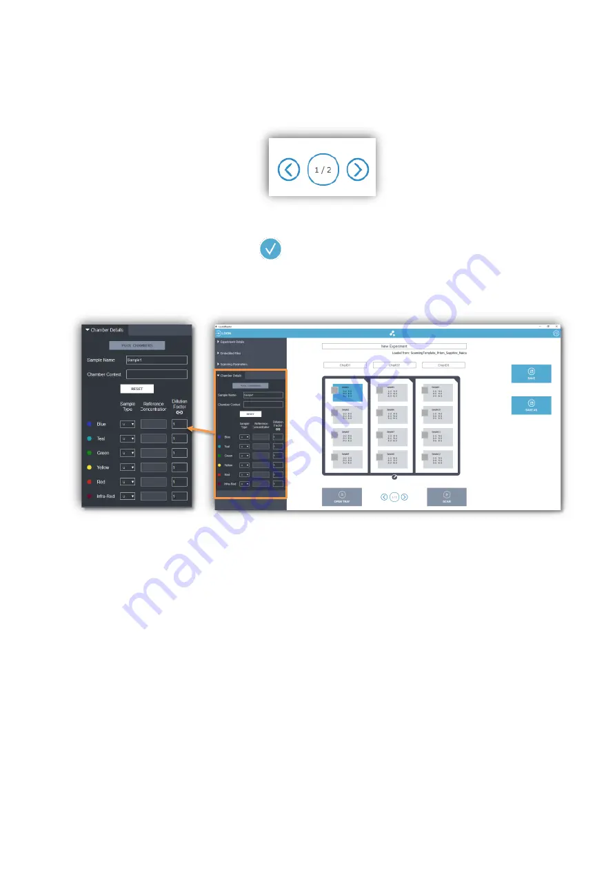
The Chambers Details panel:
Figure 16: The
“Chamber Details” form.
Enter the details of a given chamber, first click on the chamber in the rack layout (chamber
rectangle becomes blue),
proceed to edit the “Chamber Details” form
(Fig. 14
).
•
“Sample Name”: to identify sample loaded in the chamber.
A USB barcode reader can be used to autofill the chip code to gain time.
•
“Chamber Context” (optional): to enter additional information to make the scan
data unique (useful if scanning the chamber multiple times).
•
For each detection channel (“Blue”, “Teal”, Green”, “Yellow” “Red” and “Infra-Red”
LED):
-
“Sample Type” (see details below).
-
“Reference Concentration” if the Sample Type is “S” (meaning that the
target concentration is known): the expected concentration (in copies/µL).
-
“Dilution Factor” (e.g., 10 for a 10-fold dilution from the stock sample).
Then, edit the type of the sample for each given channel, the possible values are:
•
U: unknown
•
S: Standard (i.e., the stock concentration is known for the channel of interest and should be
entered in the next field in copies/µL)
•
N: Negative control (i.e., there are only negative droplets for the channel of interest)
•
P: Positive control (i.e., there are positive droplets for the channel of interest)


