41
Twin Installations
All
STEYR MOTORS GmbH Marine Engine
inboard models can also
be set up for counter-rotation for twin installation. This is done by in-
versing direction of cable lines on shift lever in order to achieve a coun-
ter-rotation of propeller.
Counter-rotation is accomplished in the gearbox. The propeller, pro-
peller shaft and output gear are the only parts that counter-rotate. The
engine always has standard rotation.
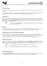
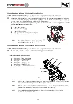
4
It is customary to operate your propeller as shown on this illus-
tration for twin installation.
Some boat manufacturers may set up twin installations the op-
posite way. When propellers and/or cable lines are removed,
care must be taken to attach them at the same position as be-
fore, and that the propellers are not exchanged.
Optional Propellers
Propellers are available in all regular sizes for both right- and
left-hand rotation. Stainless steel has greater strength and du-
rability than aluminium. This allows the stainless steel propeller
blades to be thinner and still maintain more beam strength than
aluminium propellers. The result is a more efficient propeller that
gives better performance and more fuel economy.
Propellers
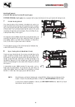
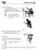
5
Right-hand propellers rotate clockwise to propel a boat forward.
Right-hand propellers are considered standard-rotation propel-
lers. To identify a right-hand propeller, note the angle
(A)
of the
blade as seen from port side.
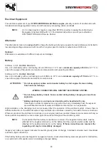
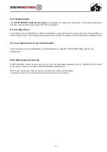
6
Left-hand propellers rotate counter clockwise to propel a boat
forward. Left-hand propellers are considered counter-rotation
propellers. To identify a left-hand propeller, note the angle
(B)
of
the blade as seen from port side.
NOTE:
Never interchange a right-hand propeller with
a left-hand propeller. This would result in the
boat being propelled in reverse when propulsion
units are operated in forward gear, and forward
when propulsion units are operated in reverse
gear. To help you better understand and show
the difference between left-hand and right-hand
propellers, see figures.
After having the propellers serviced, always shift into FORWARD or
REVERSE at idle speed and determine whether the boat moves in the
right direction. If the boat moves in the OPPOSITE direction, the pro-
pellers have not been installed properly.
CAUTION:
Failure to perform above test could result in
loss of control.
4
5
6
Summary of Contents for MO114K33
Page 2: ...This Page is intentionaly blank ...
Page 5: ...5 This page is intentionaly blank ...
Page 6: ...6 SAFETY PRECAUTIONS Safety Precautions 7 Introduction 7 ...
Page 21: ...21 This page is intentionaly blank ...
Page 49: ...49 This Page is intentionaly blank ...
Page 91: ...91 Wiring diagram MO 12 V 4 cyl from engine s n 482330250 ...
Page 92: ...92 Wiring diagram MO 24 V 4 cyl from engine s n 482330250 ...
Page 93: ...93 Wiring diagram MO 12 V 2 pol 4 cyl from engine s n 482330250 ...
Page 94: ...94 Wiring diagram MO 24 V 2 pol 4 cyl from engine s n 482330250 ...
Page 95: ...95 Wiring diagram MO E Box external 4 cyl from engine s n 482330250 ...
Page 96: ...96 Wiring diagram MO E Box external 2 pol 4 cyl from engine s n 482330250 ...
Page 101: ...101 Wiring diagram SE E Box 12V 6 cyl ...
Page 102: ...102 SE Series Wiring diagram SE E Box 24V 6 cyl ...
Page 103: ...103 SE Series Wiring diagram external SE E Box 6 cyl ...
Page 104: ...104 Wiring diagram SE E Box 12 V 4 cyl ...
Page 105: ...105 Wiring diagram external SE E Box 12 V 4 cyl ...
Page 106: ...106 Wiring diagram Instument CAN Panel 12 24V ...
Page 107: ...107 Wiring diagram Instument CAN Panel Solas 12 24V ...


