


Foreword
This service manual provides maintenance
guidelines for KYMCO AHG1 fuel injection
engine.
Chapter 1 contains all the operational
precautions that you should read carefully
before you start.
Chapter 3 gives inspection and fine-tuning tips
and maintenance of individual functions
beginning with regular inspection.
The remaining chapters outline assembly/
disassembly and inspection steps for the
engine, and electrical system.
Each chapter begins with an overall
explanation of the exploded diagram, system
diagram, maintenance troubleshooting, and
diagnosis description.
ALL
INFORMATION,
GRAPHICS
AND
SPECIFICATIONS
CONTAINED
IN
THIS
DOCUMENT ARE BASED ON THE LATEST
PRODUCT INFORMATION AVAILABLE AT THE
TIME
OF MANUFACTURE.
KWANG
YANG
MOTOR CO., LTD. RESERVES THE RIGHT TO
MAKE CHANGES AT ANY TIME WITHOUT
NOTICE
AND
WITHOUT
INCURRING
ANY
OBLIGATION WHATEVER.
ALL RIGHTS RESERVED. ANY REPRODUCTION
OR
UNAUTHORIZED
USE
WITHOUT
THE
WRITTEN PERMISSION OF KWANG YANG
MOTOR CO., LTD.IS STRICTLY PROHIBITED.
© KWANG YANG MOTOR CO., LTD.
By the Technology Training Section
First Edition
–
Jun. 2021
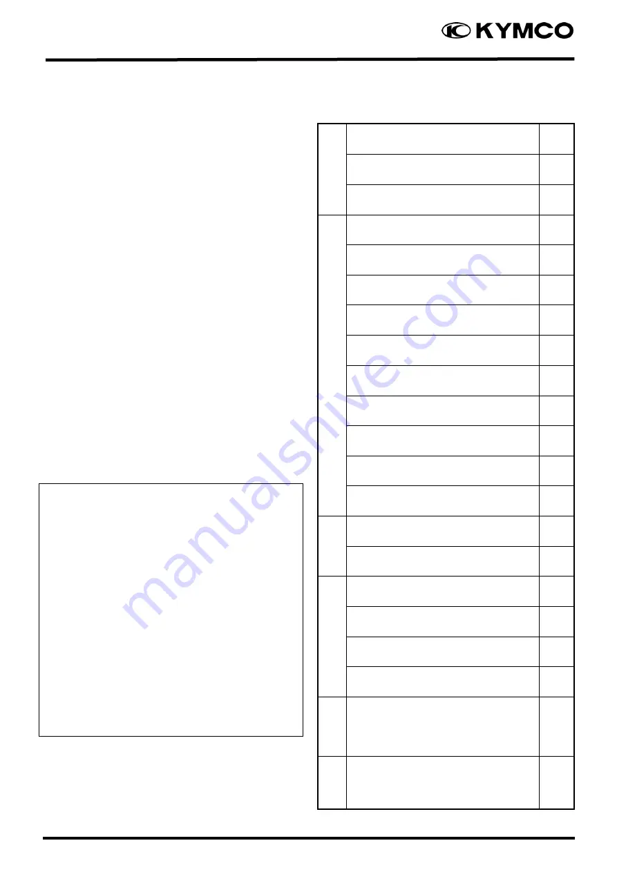
Quick Reference
1
External Components
2
Periodic Maintenance
3
En
g
in
e
Lubrication System
4
Engine Removal/ Installation
5
Cylinder Head/ Valve
6
Cylinder/ Piston
7
Drive & Driven Pulley
8
Final Reduction
9
Alternator / Start Clutch
10
Crankcase/ Crankshaft
11
Cooling System
12
Fi System
13
F
rame
Front Assembly
14
Rear Assembly
15
El
ec
tr
ica
l
Battery & Charging System
16
Ignition System
17
Starting System
18
Switches/ Lights
19
EEC
EEC System
20
A
B
S
ABS/TCS
21
Summary of Contents for AHG1
Page 3: ...1 Quick Reference 1 2 1 Engine Frame Serial Number Frame Serial Number Engine Serial Number ...
Page 14: ...1 Quick Reference 1 13 8 General Troubleshooting Engine lacks power 8 1 ...
Page 15: ...1 Quick Reference 1 14 ...
Page 16: ...1 Quick Reference 1 15 Engine will not stat or is hard to start 8 2 ...
Page 17: ...1 Quick Reference 1 16 Poor handling 8 3 ...
Page 18: ...1 Quick Reference 1 17 Poor performance at high speed 8 4 ...
Page 19: ...1 Quick Reference 1 18 Poor performance at low and idle speed 8 5 ...
Page 20: ...2 External components Exhaust pipe 2 0 2 ...
Page 21: ...2 External components Exhaust pipe 2 1 ...
Page 57: ...4 LUBRICATION SYSTEM 4 1 Lubrication System ...
Page 66: ...5 ENGINE 5 1 Engine 1 ENGINE REMOVAL INSTALLATION 4 1 1 Removal 4 1 2 Installation 6 ...
Page 73: ...6 CYLINDER HEAD VALVE 6 2 1 SCHEMATIC DRAWING ...
Page 87: ...7 CYLINDER PISTON 7 2 1 SCHEMATIC DRAWING ...
Page 97: ...8 DRIVE DRIVEN PULLEYS 8 2 1 SCHEMATIC DRAWING ...
Page 111: ...9 FINAL REDUCTION 9 2 1 SCHEMATIC DRAWING ...
Page 122: ...10 A C GENERATOR STARTER CLUTCH Downtown 125i 10 2 SCHEMATIC DRAWING ...
Page 130: ...11 Crank Case Crank Shaft 11 2 1 Schematic Drawing ...
Page 134: ...11 Crank Case Crank Shaft 11 6 Remove the oil seal from the left crankcase ...
Page 156: ...14 FRONT ASSEMBLY 14 2 1 SCHEMATIC DRAWING ...
Page 157: ...14 FRONT ASSEMBLY 14 3 ...
Page 176: ...15 REAR ASSEMBLY 15 2 1 SCHEMATIC DRAWING ...
Page 196: ...18 STARTING SYSTEM 18 2 1 Starting System Layout Battery Start Relay Start Motor ...
Page 224: ...20 ANTI LOCK BRAKE SYSTEM ABS 20 5 Pre diagnosis Inspection Chart 1 ...
Page 225: ...20 ANTI LOCK BRAKE SYSTEM ABS 20 6 Pre diagnosis Inspection Chart 2 ...