35
I
H
A
G
B
A1
A1
E
H
J
C
D
F
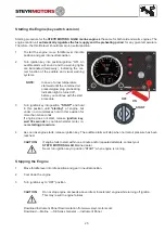
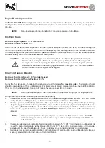
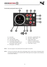
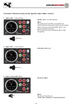
Instrument panel (push button version)
A
tachometer
F
push button - ignition ON/OFF (red)
A1
function buttons
G
push button - START (green)
B
engine parameter display
H
audible warning device
(installed on rear side of panel)
C
warning light - battery charge
D
combined light preheating control &
warning light - engine oil pressure
I
emergency cut off switch (lanyard)
J
circuit breaker (10 amp)
E
warning light - check engine
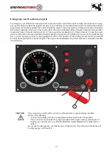
NOTE:
Instrument gauges are automatically illuminated if ignition is turned ON.
NOTE:
In the case of inversion the engine will be automatically shut off, in order to allow normal operation later.
The ignition push button (F) must be switched OFF and ON again, then the engine can be restarted via
the push button START (G).
Summary of Contents for MO114K33
Page 2: ...This Page is intentionaly blank ...
Page 5: ...5 This page is intentionaly blank ...
Page 6: ...6 SAFETY PRECAUTIONS Safety Precautions 7 Introduction 7 ...
Page 21: ...21 This page is intentionaly blank ...
Page 49: ...49 This Page is intentionaly blank ...
Page 91: ...91 Wiring diagram MO 12 V 4 cyl from engine s n 482330250 ...
Page 92: ...92 Wiring diagram MO 24 V 4 cyl from engine s n 482330250 ...
Page 93: ...93 Wiring diagram MO 12 V 2 pol 4 cyl from engine s n 482330250 ...
Page 94: ...94 Wiring diagram MO 24 V 2 pol 4 cyl from engine s n 482330250 ...
Page 95: ...95 Wiring diagram MO E Box external 4 cyl from engine s n 482330250 ...
Page 96: ...96 Wiring diagram MO E Box external 2 pol 4 cyl from engine s n 482330250 ...
Page 101: ...101 Wiring diagram SE E Box 12V 6 cyl ...
Page 102: ...102 SE Series Wiring diagram SE E Box 24V 6 cyl ...
Page 103: ...103 SE Series Wiring diagram external SE E Box 6 cyl ...
Page 104: ...104 Wiring diagram SE E Box 12 V 4 cyl ...
Page 105: ...105 Wiring diagram external SE E Box 12 V 4 cyl ...
Page 106: ...106 Wiring diagram Instument CAN Panel 12 24V ...
Page 107: ...107 Wiring diagram Instument CAN Panel Solas 12 24V ...

