42
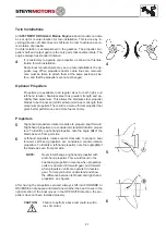
Propeller Torque
The torque of the propeller creates forces that are transmitted to the boat. This can cause the boat to lean to one
side (list).
The forces created by the counter-rotating propeller are opposite to the forces created by the standard rotating pro-
peller. When the vertical drives are trimmed equal, these opposite forces balance each other.
Propeller care
A damaged or unbalanced propeller will cause excessive vibration and a loss of boat speed. Under these conditions,
stop the engine and check the propeller for damage. If the propeller seems to be damaged, have it checked and
repaired by your local
STEYR MOTORS GmbH
Marine dealer. Always carry a spare propeller and replace the dam-
aged propeller as soon as possible.
NOTE:
Never run with a damaged propeller. Running with a damaged propeller can result in damage
to drive components and engine.
Water Jet
When using water jet drives, please contact your STEYR MOTORS GmbH Marine dealer. As to information on func-
tion and application, please refer to respective documents and documentation of the drive manufacturer.
Operating Procedure for Freezing Temperatures
When freezing temperatures are forecast and the boat will be operated and left in the water, the propeller must re-
main in the tilted down (submerged) position at all times to prevent water in the vertical drive from freezing. Upon
completion of engine operation, drain the engine as described in
Off-Season Storage Preparations
.
Salt Water Operation
Fresh water to flush the raw water circuit is recommended after use in salt, polluted, or brackish water to prevent
deposits from clogging and corroding the cooling passages. Contact your
STEYR MOTORS GmbH
Marine dealer to
obtain an Engine Flushing Kit that allows flushing of the engine when in or out of the water.
NOTE:
Use in salt or brackish water may require additional anti-corrosion protection.
NOTE:
START and RUN Diesel-Engine while raw water circuit is flushed with fresh water!
High Altitude Operation
Your
STEYR MOTORS Gmb
H
Marine Engine is specified to operate within an altitude from a sea level of 1000 me-
ters without any performance loss. Operation in altitudes above 1000 meters are not recommended.
Summary of Contents for MO114K33
Page 2: ...This Page is intentionaly blank ...
Page 5: ...5 This page is intentionaly blank ...
Page 6: ...6 SAFETY PRECAUTIONS Safety Precautions 7 Introduction 7 ...
Page 21: ...21 This page is intentionaly blank ...
Page 49: ...49 This Page is intentionaly blank ...
Page 91: ...91 Wiring diagram MO 12 V 4 cyl from engine s n 482330250 ...
Page 92: ...92 Wiring diagram MO 24 V 4 cyl from engine s n 482330250 ...
Page 93: ...93 Wiring diagram MO 12 V 2 pol 4 cyl from engine s n 482330250 ...
Page 94: ...94 Wiring diagram MO 24 V 2 pol 4 cyl from engine s n 482330250 ...
Page 95: ...95 Wiring diagram MO E Box external 4 cyl from engine s n 482330250 ...
Page 96: ...96 Wiring diagram MO E Box external 2 pol 4 cyl from engine s n 482330250 ...
Page 101: ...101 Wiring diagram SE E Box 12V 6 cyl ...
Page 102: ...102 SE Series Wiring diagram SE E Box 24V 6 cyl ...
Page 103: ...103 SE Series Wiring diagram external SE E Box 6 cyl ...
Page 104: ...104 Wiring diagram SE E Box 12 V 4 cyl ...
Page 105: ...105 Wiring diagram external SE E Box 12 V 4 cyl ...
Page 106: ...106 Wiring diagram Instument CAN Panel 12 24V ...
Page 107: ...107 Wiring diagram Instument CAN Panel Solas 12 24V ...

