37
1
Emergency cut off switch (Lanyard)
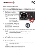
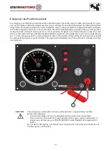
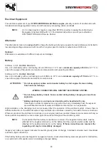
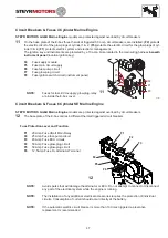
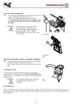
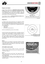
An emergency cut off switch is a feature on the instrument panel. Use of this switch is highly recommended. To prop-
erly use this feature, attach the lanyard securely to your clothing. Do not attach the lanyard to clothing that will tear
away before the lanyard is pulled from switch to stop the engine. Using this switch is simple and should not interfere
with normal operation of the boat. Care must be taken to avoid accidental pulling of lanyard during normal operation.
Unexpected loss of forward motion will occur. This could allow occupants to be thrown forward. In case the emer-
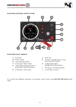
gency cut off switch had been activated (lanyard pulled) the engine can be restarted by a person if; the pull knob (fig.
pos. 1) of the emergency switch is being pulled and held in this position. While holding the pull knob proceed with
the normal start procedure and start engine. The engine will immediately stop if the pull knob is released under this
circumstances.
CAUTION:
The emergency cut off switch can only be effective when in good working condition.
Observe the following:
* Lanyard must always be free of entanglements that could hinder its operation.
* Once a month, check switch for proper operation. With engine running, pull lanyard. If
engine does not stop, see your STEYR MOTORS GmbH DEALER for replacement of
switch.
Do not use the Emergency cut off switch as a "Stop"-switch. This will reduce the life time of
the Emergency cut off switch!
Summary of Contents for MO114K33
Page 2: ...This Page is intentionaly blank ...
Page 5: ...5 This page is intentionaly blank ...
Page 6: ...6 SAFETY PRECAUTIONS Safety Precautions 7 Introduction 7 ...
Page 21: ...21 This page is intentionaly blank ...
Page 49: ...49 This Page is intentionaly blank ...
Page 91: ...91 Wiring diagram MO 12 V 4 cyl from engine s n 482330250 ...
Page 92: ...92 Wiring diagram MO 24 V 4 cyl from engine s n 482330250 ...
Page 93: ...93 Wiring diagram MO 12 V 2 pol 4 cyl from engine s n 482330250 ...
Page 94: ...94 Wiring diagram MO 24 V 2 pol 4 cyl from engine s n 482330250 ...
Page 95: ...95 Wiring diagram MO E Box external 4 cyl from engine s n 482330250 ...
Page 96: ...96 Wiring diagram MO E Box external 2 pol 4 cyl from engine s n 482330250 ...
Page 101: ...101 Wiring diagram SE E Box 12V 6 cyl ...
Page 102: ...102 SE Series Wiring diagram SE E Box 24V 6 cyl ...
Page 103: ...103 SE Series Wiring diagram external SE E Box 6 cyl ...
Page 104: ...104 Wiring diagram SE E Box 12 V 4 cyl ...
Page 105: ...105 Wiring diagram external SE E Box 12 V 4 cyl ...
Page 106: ...106 Wiring diagram Instument CAN Panel 12 24V ...
Page 107: ...107 Wiring diagram Instument CAN Panel Solas 12 24V ...

