HLG01 Page
1
V1.0
© 2007 Stevens AeroModel. All Rights Reserved.
HLG01
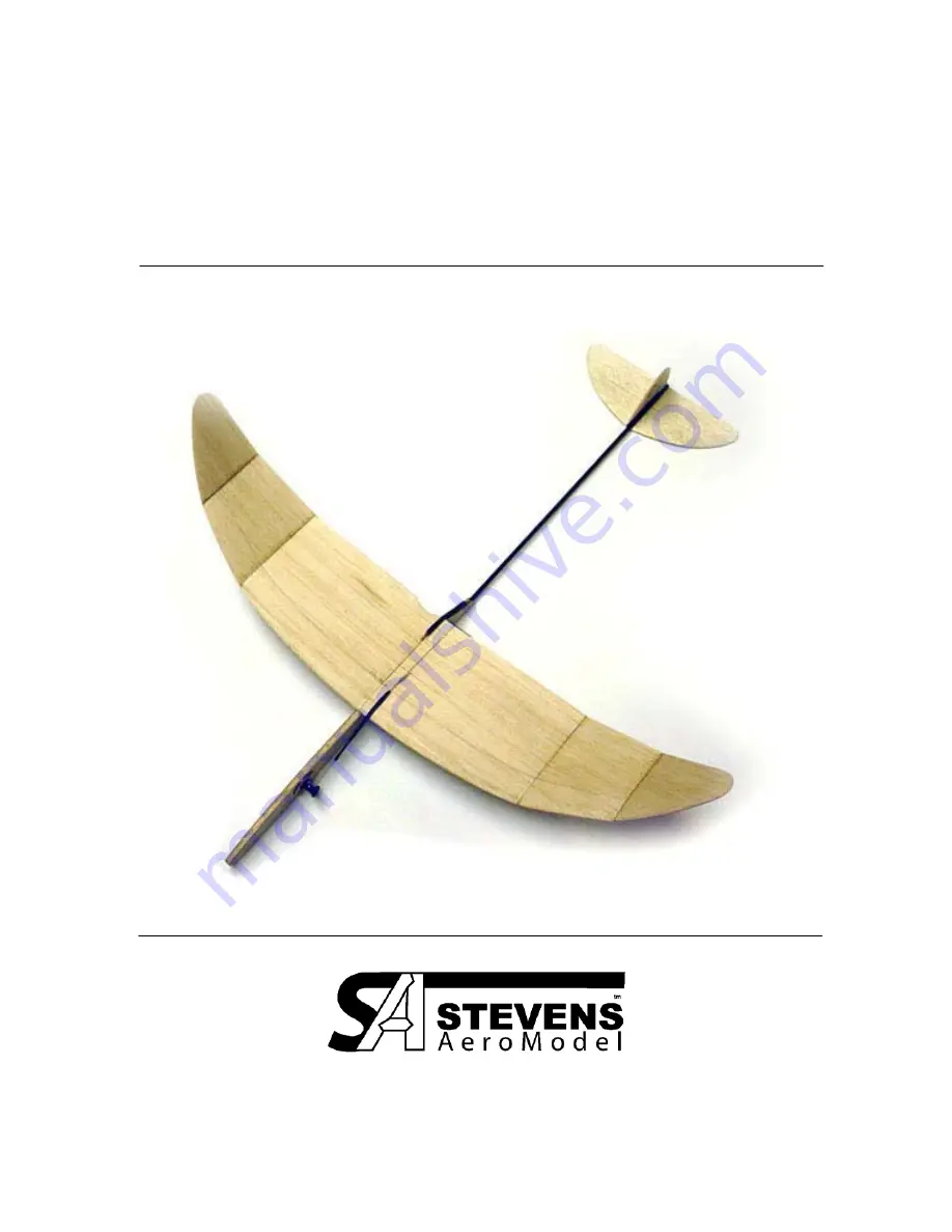
Hand Launch Glider #1
Span 18 in. / Length 19-3/8 in. / Area 46.5 sq. in. / Typical Flying Weight 25g
Page 1: ...HLG01 Page 1 V1 0 2007 Stevens AeroModel All Rights Reserved HLG01 Hand Launch Glider 1 Span 18 in Length 19 3 8 in Area 46 5 sq in Typical Flying Weight 25g...
Page 2: ...odel reserves the right to change or modify this warranty without notice In that Stevens AeroModel has no control over the final assembly or material used for final assembly no liability shall be assu...
Page 3: ...t pocket integrated into nose of glider Outstanding performance ideal for entry level competition use Kit Contents Illustrated Instruction Manual and Trim Guide Laser cut sheet wood bundle o HLG01 010...
Page 4: ...this product Parts Orientation When an instruction details a right or left side of the model this is always referenced from the perspective of standing behind the aircraft looking at the top of the m...
Page 5: ...unit using a sanding block and or a razor plane to produce a flat taper from the etched high point aft to the trailing edge Next round the wing from the high point forward to the leading edge Use the...
Page 6: ...iven for use of the jigs for sanding wing panel 1 Complete remaining panels in the same fashion A Sand edge using 5 degree jig B Sand edge using 10 degree jig C Sand edge using 10 degree jig A B B C C...
Page 7: ...left side wing panel 1 up at proper angle Make certain that wing panels meet flush at wing center section correct fit if required Once proper fit has been achieved wick thin CA glue along center secti...
Page 8: ...elage components we will refer to these from left to right in the photo below Notice that the major fuselage components assemble to create the following A pocket for ballast which is left open on the...
Page 9: ...alignment holes then cut and sand flush with outside surface of fuselage 3 Assemble the pop up tail boom Locate the 1 8 laser cut hardwood fuselage pivot in your parts bag and 13 1 4 length of 1 8 di...
Page 10: ...p up tail boom assembly 5 Final installation of your properly fit pop up tail involves installing the 1 8 aluminum rivet through the fuselage sides capturing the pop up tail block and securing the riv...
Page 11: ...g thin CA glue DO NOT ALLOW GLUE WITHIN 1 16 aluminum tube 7 Timer mechanism assembly Insert 1 T Pin through aluminum tube as illustrated first photo With T Pin bottomed out against back side of timer...
Page 12: ...t second photo Then slide bushing down on aluminum shaft as illustrated third photo Use wire cutters to clip the remaining length of T Pin even with the outside edge of the timer top assembly fourth p...
Page 13: ...g guide Cut one of your T Pins 1 8 from base of T as illustrated below save the remnant T Pin metal for later use Using a small blade or common tip screw driver slightly expand the loops that form the...
Page 14: ...erienced we have chosen the 1 16 stock to allow you adequate material to airfoil these parts 2 Protect completed stabilizer assembly with wood finish spray in the same manner as completed in Step 5 of...
Page 15: ...tep 1 as viewed from rear of model Once satisfied with installation apply liberal amounts of thin CA glue to adjoining surfaces of wing and fuselage Allow glue to cure then re apply 1 8 in 3 Finger re...
Page 16: ...h trailing edge of Left wing panel just outside of the first dihedral break third photo Lefties You will install wash in wedge to Right wing panel 5 Pop Up spring forward lug assembly From the remaini...
Page 17: ...rbon rod flush to the wing trailing edge as illustrated Glue with thin CA glue 7 Put the pop in pop up Select two small rubber bands from the included rubber band assortment and stretch over Pop Up sp...
Page 18: ...mplete your glider Remember the DT line will always tie off on the opposite side of the timer Wrap the string over the carbon reinforced trailing edge of wing underneath and forward to pass through th...
Page 19: ...response to the load placed on the pin When the timer reaches the two o clock position it will release the rubber band 13 Balance model Two tiny laser cut holes have been cut central to wing panel 1 a...
Page 20: ...HLG01 Page 20 V1 0 2007 Stevens AeroModel All Rights Reserved...
Page 21: ...HLG01 Page 21 V1 0 2007 Stevens AeroModel All Rights Reserved Trim Guide Hand Launch Glider 1 Span 18 in Length 19 3 8 in Area 46 5 sq in Typical Flying Weight 25g...
Page 22: ...d the rotating pin of the timer The DT string must capture the leading edge of the pop up fuselage boom to prevent it from rotating to the vertical position Release the pin and your timer will begin t...
Page 23: ...he horizon when suspended from this point Balance is easily achieved by filling ballast pocket at nose of glider with clay ballast Alternatively lead shot may be mixed with clay to reduce the bulk of...
Page 24: ...ior to release of DT string Grasp the model with your thumb and middle finger on either side of the fuselage Rest you index finger on the finger rest pocket Release the timer If a light breeze is pres...
Page 25: ...throwing Do be mindful of what is down wind from you Always throw from the up wind portion of the field Do not continue to throw a model that is out of trim as each crash risks damage to your model Al...
Page 26: ...d down CG too far forward Remove nose weight until slower glide is obtained Model glides nicely from level toss Launches are high but model fails to consistently roll left into transition Not enough l...
Page 27: ...rovements to kit design and instructions based upon your valuable feedback This project would not have been possible without the support and mentorship of local free free flight community and enthusia...