58
10.0
HOW TO CHANGE A FEATURE SETTING
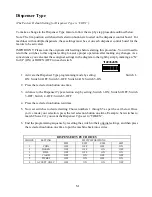
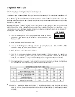
Appendix “A” which follows this section, simplifies the process of changing a feature if you so desire.
The step by step procedures allows you to insert your “choice” or “choices” for the feature(s) you want
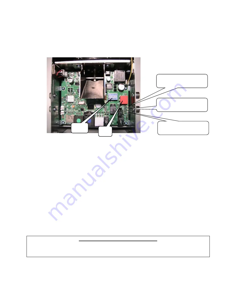
to change. The photo below illustrates the components that are used for programming, followed with
a description of their use.
Step Indicator
- The yellow or top LED is the
Step
indicator
. During the programming sequence,
this LED flashes a code indicating which
Step
you are on or when flashing in unison with the red
LED indicating which group you are in.
Choice Indicator
- The red or bottom LED is the
Choice indicator
. During the programming
sequence, this LED flashes a code that can be used to lookup the current choice for a given
feature, or when flashing in unison with the yellow LED, will indicate which group you are in.
Push Button
– The push button is used to enter a new setting (shown on the DIP switch) into the
dispenser memory. This same button is also used to advance to the next
Step
.
DIP Switches –
The dispenser includes a 5 position switch (see picture above) that is located on
the dispenser circuit board which is used during the programming sequence. It is very important,
be sure to return all five switches back to the original (
Operating Mode
) settings upon completion
of the programming process.
RESTORING THE FACTORY SETTINGS
If at any time you wish to set all of the
Feature Choices
back to the factory setting, you can do so
by setting SW1-SW5 to the UP position, and pressing the push button one time. The Status/Step
LED will flash a one. This will set all features back to the factory default settings.
DIP
Switches
Push
Button
Yellow LED:
(Step Indicator)
Green LED:
(Power)
Red LED:
(Choice Indicator)


