background image

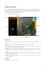
Layers:

 The Layers menu is used to configure how the aircraft icon and waypoints are displayed on the map. Under this menu is

also where you can toggle the terrain view and load KM L overlays.

Mission:

 In the mission menu, you can change the flight mode to Auto, restart the mission, or select an individual item in your

mission to fly to.

Land:

 Select land to begin your planned landing or to execute an emergency landing.

Guided:

 The Guided flight mode is a 'fly here' mode. In Guided, you choose a spot on the map that the aircraft flies to and circles.

Rally:

 The Rally flight mode is automatically used when the aircraft completes its mission or a failsafe activates. You can also

select the Rally flight mode. In this flight mode, the aircraft will navigate to the nearest Rally point and circle.

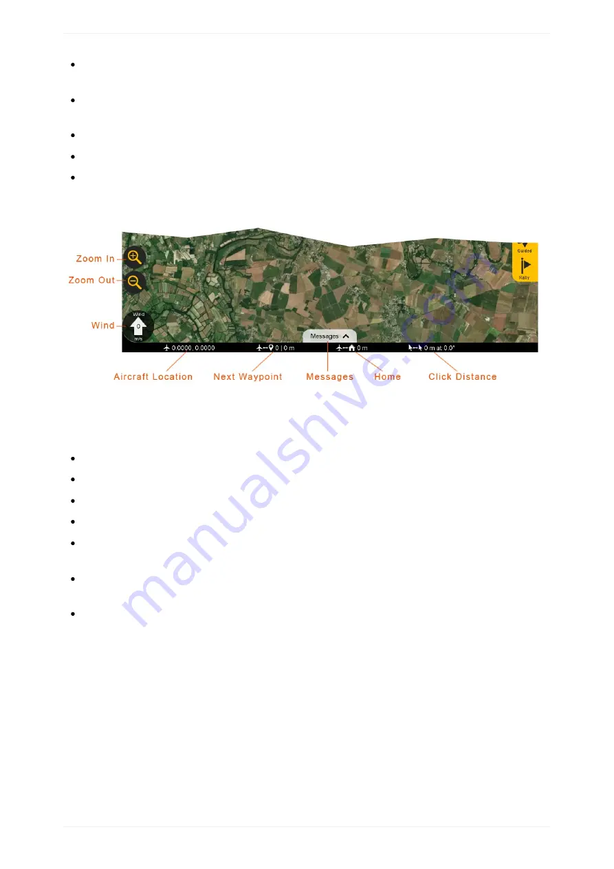
Bottom Status Bar

Displays aircraft location and waypoint information.

Zoom in/Out:

 Zooms the map area in or out. On touchscreen devices, you can also use ‘pinch-zoom’.

Wind:

 Displays the wind velocity and direction that the wind is blowing.

Aircraft Location:

 Current aircraft location coordinates shown in decimal degrees format.

Next Waypoint:

 Displays the next waypoint number in your mission and the distance to that waypoint from the aircraft.

Messages:

 The message panel displays warnings and notifications from the 

GCS

 and autopilot. A new warning will automatically

expand the message panel if it was collapsed.

Home:

 Shows the distance from the aircraft to home. If you have a tablet with built-in 

GPS

, this can be toggled to show the

distance from the aircraft to your location.

Click Distance:

 Click distance shows the distance between your last two mouse clicks. This is a quick and useful tool for

planning purposes such as determining how far away something is on the map.

GCS Overview

23

Summary of Contents for Lynx VTOL

Page 1: ...tures Getting Started GCS Overview Preflight Flying Mission Planning Changing Flight Modes Available Flight Modes Data Links Reconnecting in Flight Failsafes Warnings Landing Payloads Standard Mapping...

Page 2: ...1 15 9 1 16 1 16 1 1 16 2 1 16 3 1 16 4 1 16 5 1 16 6 1 16 7 Calibration Appendixes Simulator Flying with other GCS s Status LED Meanings Getting Logs System Limitations Manual Changelog Glossary 2...

Page 3: ...Lynx VTOL User Manual Last Updated 18 November 2019 Copyright 2013 2019 Swift Radioplanes LLC APDF version of this manual is available here Introduction 3...

Page 4: ...ANY OTHER THEORY OF LIABILITY EVEN IF SWIFT RADIOPLANES HAS BEEN ADVISED OF SUCH DAMAGES Further in no event shall the liability of Swift Radioplanes exceed the individual price of the Product on whic...

Page 5: ...g Lynx VTOL blends the ease of use and flexibility of a multirotor with the endurance and speed of an airplane This revision of the manual refers to version 0 6 0 of Swift GCS software Check the softw...

Page 6: ...Package Contents Package Contents 6...

Page 7: ...r wing Left wing Right wing Stabilator horizontal tail Left VTOL motor boom Right VTOL motor boom 4x Lithium Ion battery packs main battery 2x Lithium Polymer battery packs VTOL battery Battery charge...

Page 8: ...rs Micro SD card adapter USB micro cable USB C cable Ground telemetry radio with antennas RC controller optional Gamepad optional Payload optional GNSS base station optional GeoTagz license and dongle...

Page 9: ...rolling the how the aircraft turns in flight The wings are detachable from the center wing Center Wing The center wing connects to the top side of the fuselage and joins the entire wing and VTOL motor...

Page 10: ...or landing and whenever possible while the aircraft is powered on VTOL Propeller Used to generate thrust for vertical takeoffs and landings Camera Lens Cutout Lynx VTOL features downward facing camer...

Page 11: ...geo tagging images Status LED This colored LED indicates the status of the autopilot Telemetry Antenna Used by the aircraft to communicate with Swift GCS via the ground telemetry radio The antenna is...

Page 12: ...ries Lynx VTOL uses one pair of main batteries That main battery is split into two packs to comply with air cargo and airline restrictions The two main batteries are connected in series and power the...

Page 13: ...adio The telemetry radio communicates with the aircraft on the ground and in flight RC Controller The RC controller enables the safety pilot to optionally fly the aircraft in assisted modes Hardware F...

Page 14: ...ideally suited for field tablets and requires minimal computing hardware to run New users are guided through the flying process via the built in checklist and preflight steps Survey planning is fully...

Page 15: ...GeoTagZ preforms PPK corrections and photo tagging for PPK enabled Lynx VTOL systems If the aircraft is not PPK enabled GeoTagZ is not needed or provided Software Features 15...

Page 16: ...n future updates 3 Launch the newly installed GCS 4 The GCS will prompt you for a Mapbox token If you do not already have a Mapbox token sign up for an account here After signing up for Mapbox you can...

Page 17: ...versions You can opt out of this behavior by selecting the Settings Tab then select the GCS entry and uncheck Report anonymous usage and errors Windows Telemetry Driver Configuration The default setti...

Page 18: ...3 Right click on the USB Serial Port and select properties Getting Started 18...

Page 19: ...4 Swap to the Port Settings tab and select Advance Getting Started 19...

Page 20: ...erial Enumerator option and select OK Installing GeoTagZ 1 Download the most recent version of GeoTagZ and the manual here 2 Follow the instructions in the manual to install and configure GeoTagZ Gett...

Page 21: ...used to perform a preflight on your Lynx VTOL prior to every takeoff Plan The Plan tab is used add waypoints survey grids actions or rally points to your mission The Plan tab is utilized during the pr...

Page 22: ...ode Timer Displays the current flight in Hours Minutes Seconds The timer automatically starts on takeoff and stops when the aircraft lands and disarms The aircraft must be restarted turned off and on...

Page 23: ...Bottom Status Bar Displays aircraft location and waypoint information Zoom in Out Zooms the map area in or out On touchscreen devices you can also use pinch zoom Wind Displays the wind velocity and di...

Page 24: ...eed of the aircraft relative to the ground The unit for both ground and airspeed is displayed below Ground speed is affected by wind Airspeed The speed of the aircraft relative to the air through whic...

Page 25: ...on in the sky The aircraft will fly through or near the waypoint and then proceed to the next item in your mission Waypoints are automatically generated when creating a survey Survey Polygon A survey...

Page 26: ...all drone that cannot fly in heavy rain or strong wind conditions In case of doubt make sure to check a weather bulletin including wind estimations in the flight area Note that wind is often stronger...

Page 27: ...s attached to the fuselage and that the tube is free of obstructions Check the hoses behind the pitot tube for kinks or damage Main Propeller Fold the propeller blades outward after removing the fusel...

Page 28: ...Inside Bays Ensure the inside of the fuselage especially within the battery connectors is free of dust and debris VTOL Propellers Inspect the propeller blades for chips or other damage Preflight 28...

Page 29: ...or other damage Tail Clips Inspect the tail clips for cracks and ensure that they are securely fastened Center Wing Inspect the center wing for cracks or other damage Inspect the wing to fuselage con...

Page 30: ...adio USB to your GCS computer The standard Lynx VTOL telemetry radio frequency uses 915 MHz The antennas should be spaced apart 90 degrees from each other for best reception RC Controller Verify and T...

Page 31: ...number controller s battery and stopwatch Ensure the tail number displayed matches your aircraft and that the controller is charged The standard Lynx VTOL RC controller frequency uses 2 4GHz Battery C...

Page 32: ...s armed taking off or landing and whenever possible while the aircraft is powered on Caution The battery connectors are keyed and only fit one way Forcing the battery into the wrong orientation may da...

Page 33: ...anings section for more details on the status LED Autopilot Connect Wait until the telemetry radio s status LED displays solid green blinking red before proceeding Press the Connect button on the Chec...

Page 34: ...higher or lower than the default altitude At this time Lynx VTOL does not support terrain following Choosing the appropriate flight altitude for your mission is critical and dependent upon imagery re...

Page 35: ...t will automatically weathervane to face the wind during the vertical climb and transition Caution Lynx VTOL has a limited battery capacity for the VTOL motors If the takeoff altitude is too high the...

Page 36: ...cles that are near or higher than your transition altitude when planning the location The landing pattern is automatically generated The heading is affected by the wind direction Similar to a takeoff...

Page 37: ...ansition altitude is 30 meters The area within the landing circle must be free of obstacles near or above the transition altitude Heading Upon reaching the transition altitude the aircraft will pick a...

Page 38: ...on reaching the ground the aircraft will automatically disarm and stop spinning the motors after a short delay Landing procedure seen from the side Caution Lynx VTOL has a limited battery capacity for...

Page 39: ...section describing the rally mode Caution If there are no rally points within 5 kilometers of the aircraft during a failsafe or if you choose the flight mode rally the aircraft will fly to home and c...

Page 40: ...tagging Step 1 Press the Sync button to begin the process Step 2 The GCS will prompt you to ensure that the camera is installed and connected to the aircraft Press Yes button to proceed Step 3 The GCS...

Page 41: ...estarting the process Aircraft Assemble This step will walk you through assembling your Lynx VTOL Step 1 Attach one of the motor booms to the center wing by sliding it against the spar joiners Loosen...

Page 42: ...your shoe such that the wing is standing vertically Align the motor boom with the spar joiner and press down Caution Do not force the motor boom if the connectors do not align Instead wiggle the motor...

Page 43: ...Step 2 Tighten the 2x motor boom thumbscrews to secure it against the center wing Step 3 Attach the other motor boom using the same process Preflight 43...

Page 44: ...e of the wings to the center wing by sliding it against the spar joiners Keep sliding the wing against the center wing until the wing clip engages The wing should now be nearly flush with the motor bo...

Page 45: ...e leading edge of a wing with your other hand Line up the spar joiners and slide the wing together Caution Do not force the wing if the aileron connectors do not align Instead wiggle the wing until th...

Page 46: ...e wing and align it to the bolt threads Once aligned gently press down on the wing until the fuselage to wing connector is fully seated The VTOL motors will audibly beep when the connector is seated C...

Page 47: ...Step 8 Secure the wing to the fuselage by inserting and finger tightening the wing thumbscrews There are three wing thumbscrews The two in the front are longer than the rear one Preflight 47...

Page 48: ...nd aircraft continue to agree No warnings should be triggered while performing this check Caution If the heading is off from where the aircraft is actually pointing by 10 degrees or more you may need...

Page 49: ...t This step verifies that the initial mission item is set to a takeoff Control Surfaces Enable This enables the aileron rudder and stabilator flight control surfaces to move Throttle will still be dis...

Page 50: ...upsets Do this by observing how the flight control surfaces react to rotations in all three axes pitch roll and yaw heading The control surfaces should oppose the movement in each direction For exampl...

Page 51: ...No Warnings Verify Ensure that there are no warnings before takeoff All warnings must be resolved Preflight 51...

Page 52: ...off area should be clear of bystanders and obstacles Notify everyone participating in the flight that the aircraft is about to takeoff Aircraft Takeoff This step arms the aircraft and then immediately...

Page 53: ...t will cause the autopilot to automatically abort the takeoff Warning Arming the aircraft allows the autopilot to spin propellers Arming finalizes your home location The aircraft must pass a series of...

Page 54: ...thrust generated by the VTOL propellers on takeoff and landing can kick up dust and loose debris Use a landing pad or similar to reduce the amount of dust when flying from dusty environments Preflight...

Page 55: ...Flying GCS Overview Mission Planning Changing Flight Modes Available Flight Modes Data Links Reconnecting in Flight Warnings Failsafes Flying 55...

Page 56: ...photos may need to be deleted before processing Settings for the survey mission can be modified by expanding the survey item in the list of mission items Camera Expand to reveal the list of existing c...

Page 57: ...ult values of 110 meters lead in and 150 meters overshoot are suitable for Lynx in most cases Statistics Survey statistics will display information about your survey and polygon The field of view FOV...

Page 58: ...or example if the aircraft is in Auto but the Safety Pilot changes to Cruise the aircraft will enter Cruise If then the GCS Operator changes back into Auto the aircraft will enter Auto even though the...

Page 59: ...ate image overlap To do so expand the list of waypoints under Mission and select the first waypoint of the line you want to refly Changing between Vertical and Forward Flight Modes If the aircraft is...

Page 60: ...while transitioning to a hover depends upon the ground speed of the aircraft Configuring Modes on the RC Controller Not all modes listed below are available on the RC controller as standard The stand...

Page 61: ...Caution Only select from modes described in the Lynx VTOL manual Cruise FBWB QLoiter QLand Other modes are strictly reserved for testing Changing Flight Modes 61...

Page 62: ...e adjusted by clicking on the Guided button Applications allows the GCS operator to intervene with a point and click interface avoiding other air traffic climb descend at a specific location holding p...

Page 63: ...sswind allowing the safety pilot to point the aircraft at a distant object and accurately track to that object As such Cruise requires GPS to maintain ground course Applications allows the safety pilo...

Page 64: ...bypasses all forms of autopilot stabilization In this mode the safety pilot is completely responsible for flying like an RC airplane This gives the safety pilot the most control for an emergency scen...

Page 65: ...he autopilot cannot recover from Forward Flight Mode Comparison Forward Modes Auto Rally Guided Cruise FBWB Manual Interface GCS GCS GCS Controller Controller Controller Link Telem Telem Telem RC RC R...

Page 66: ...pitch limit Weathervaning and forward assist are enabled in QLoiter If the aircraft is in forward flight when this mode is entered it will transition to a hover Applications allows the safety pilot to...

Page 67: ...de As such it does not require GPS It is not possible to roll the aircraft past the roll limit and it is not possible to pitch the aircraft beyond the pitch limit QLoiter is recommended over QStabiliz...

Page 68: ...RC Controlled by Mission Sticks Sticks Sticks Autonomous x x Stabilized Inputs x x GPS Required x x x Position Control x x x Altitude Control x x x Stick Nudging x Weathervaning x x x Forward Assist x...

Page 69: ...point the aircraft into the wind prior to takeoff to increase performance The aircraft will also use the main motor when 2 meters above the ground to help maintain its position in higher winds This is...

Page 70: ...link before the failsafe activates The default failsafe timeout for the telemetry radio is 15 seconds This means that 15 seconds after you lose link the aircraft will change flight modes to Rally and...

Page 71: ...radio interference that will greatly decrease range Note the absence of this warning during preflight does not mean that radio interference is not possible RC You may occasionally lose the connection...

Page 72: ...together if you are not using turned off the RC controller DO NOT disable the RC failsafe if you are using the RC controller Warning Disabling the RC failsafe when the RC controller is being used may...

Page 73: ...ight following a GCS crash or computer issue 1 Reboot your computer and or restart Swift GCS 2 Go to Checklist Tab Connect Auto Detect to reconnect to the aircraft 3 Assuming you have tripped your tel...

Page 74: ...4 Go to Plan Tab Download to visualize your waypoints 5 Note the last waypoint the aircraft was going to prior to Rallying Reconnecting in Flight 74...

Page 75: ...epeat the last flight leg to ensure adequate image overlap To do so expand the list of waypoints under Mission and select the waypoint preceding the waypoint mentioned in step 5 Reconnecting in Flight...

Page 76: ...ies Critical battery The main battery has been below 15 0V for 10 seconds The aircraft will automatically perform an emergency landing in place QLand Caution The aircraft should always be landed befor...

Page 77: ...sume too much VTOL battery capacity to safely continue the mission It may have enough to finish the takeoff but may not have enough remaining capacity to land The aircraft will automatically perform a...

Page 78: ...f this failsafe activates repeatedly something is wrong with the forward propulsion The aircraft should be brought back to the preplanned landing as this failsafe rapidly consumes the VTOL battery Fai...

Page 79: ...he ground first try restarting the aircraft If the problem persists power down the aircraft and reformat the SD card If this happens during flight you may safely continue flying but no autopilot data...

Page 80: ...and reduce noise or begin the preplanned landing sequence High autopilot temperature The autopilot is excessively warm If on the ground power off the system and let it cool before restarting the pref...

Page 81: ...a new landing point with other GCS s insert a DO_LAND_START before the landing item PreArm Missing mission item vtol takeoff A takeoff must have been planned before arming the aircraft Plan a takeoff...

Page 82: ...ce the amount of dust when flying from dusty environments Once on the ground the aircraft will continue to spin the motors at idle for a few seconds and then automatically disarm and disable the fligh...

Page 83: ...rm once the aircraft has landed or you can manually disarm it Do not disarm the aircraft while flying This will result in a crash Mode Manual Move the mode switch on the RC controller to manual Wing R...

Page 84: ...e Disassemble the aircraft Hold the center wing horizontally and flat against your stomach Point the leading edge front of the wing down Holding the center wing with one hand and grasp the leading edg...

Page 85: ...he center wing The thumbscrews do not need to be completely removed from the motor boom They are held in place by the motor boom for convenience Grab the motor boom with both hands and press against t...

Page 86: ...Landing 86...

Page 87: ...Payloads Standard Mapping Payload Multispectral Mapping Payload Custom Payloads Payloads 87...

Page 88: ...GB Lens Interchangeable 20mm as setup GSD at 90 m 300 ft 1 76 cm px GSD at 120 m 400 ft 2 34 cm px Coverage at 90 m 300 ft 3 3 km2 815 acres 60 sidelap Coverage at 120 m 400 ft 4 5 km2 1100 acres 60 s...

Page 89: ...ing the Camera The compass on Lynx VTOL can be sensitive to payload changes and may require a compass calibration once your custom payload is installed within the payload bay See the Calibration secti...

Page 90: ...misalignment However do not force the connector into place Doing so may damage the fuselage or camera mount Removing the Camera To remove the camera from the mount 1 Disconnect the feedback connector...

Page 91: ...SD Card and Battery The camera s SD card and battery are located on the bottom of the camera behind a hinged door Standard Mapping Payload 91...

Page 92: ...MENU button Change the settings as indicated below When finished turn the camera off using the ON OFF switch to save your settings Turning the camera off by ejecting the battery may not save the setti...

Page 93: ...1 Airplane Mode On App Icon n a n a Playback Icon n a n a Briefcase Icon 1 Monitor Brightness Manual 2 PWR Save Start Time 30 Min 3 Remote Ctrl On Physical Modifications The lanyard anchor on the righ...

Page 94: ...Standard Mapping Payload 94...

Page 95: ...icaSense which can be found here Technical Specifications RedEdge MX Specs Sensor RGB RE NIR narrowband Lens 5x fixed 5 5mm GSD at 90 m 300 ft 6 14 cm px GSD at 120 m 400 ft 8 18 cm px Coverage at 90...

Page 96: ...alibration once your custom payload is installed within the payload bay See the Calibration section for more information The camera mount is secured within the aircraft using 4x 6 32 x 3 8 inch screws...

Page 97: ...1 Insert the mount into the payload connector 2 Secure the mount to the payload bay using the 4x mounting screws Multispectral Mapping Payload 97...

Page 98: ...ier to use one with a longer reach 4 Attach the DLS to the top of fuselage just behind the GPS hatch as shown connector must face forward using doubled sided tape or adhesive backed Velcro Velcro will...

Page 99: ...n the GPS hatch You may need to undo the GPS hatch screws to route the DLS wire On Lynx VTOL 079 and older contact support srp aero Triggering the Camera The camera can be triggered manually with the...

Page 100: ...es an image manually or from the autopilot the status light on the DLS will flash blue This is your only cue as to whether or not an image was taken during the payload check preflight step Multispectr...

Page 101: ...llows you to access the camera s SD card while the camera is installed within the aircraft To access the SD card simply loosen the thumbscrew and pivot the camera upward Tighten the thumbscrew before...

Page 102: ...ge MX Geo Tagging Multispectral Images Multispectral imagery is automatically geo tagged in flight using the autopilot s GPS and heading data Additional processing is only required if PPK accuracy is...

Page 103: ...a browser and type the default IP of 192 168 10 254 in the address bar to open the MicaSense Camera App 2 Go to the settings tab 3 Under Auto Capture Mode select Ext Trigger 4 Under Ext Trigger Mode s...

Page 104: ...photos 1 Go to the home tab 2 Check that you have enough space on the SD card before flying 3 Under GPS Sats you will notice that 0 satellites are being used this is because the camera is getting GPS...

Page 105: ...5 On the camera tab you can view the camera s field of view or manually capture photos Multispectral Mapping Payload 105...

Page 106: ...meet the following requirements Fit within the volume of the payload bay Must not exceed 500 grams 1 10 lbs in weight Must not exceed power requirements Must not draw power from the VTOL battery Must...

Page 107: ...l Signal Notes 1 VBatt LiIon 15 to 25 2V at 3A 2 AutoPilot Power 5 3V at 1A 3 Event Aux 3 0 to 3 3V at 10mA also routes to GPS event input 4 Trigger Aux 6 0 to 3 3V at 10mA 5 Serial2 Tx 0 to 3 3V at 5...

Page 108: ...Mounting Custom Payloads 108...

Page 109: ...flow channel that extends from camera lens cutout to the autopilot Failure to do so may result in the autopilot overheating in flight Caution When using the mounting threads ensure that your mounting...

Page 110: ...Post Processing Geo Tagging PPK Tagging Base Station Reference Stations Post Processing 110...

Page 111: ...bay only required with Standard Mapping Payload Once removed both the autopilot and GPS micro SD cards are accessible Either will work for geo tagging position data but only the autopilot log will ta...

Page 112: ...ould be saved to 6 If EXIF tags need to be written as well this can be done by checking the box under Advanced options 7 Select tag photos to begin the tagging process Once complete the results will b...

Page 113: ...e that specific image and more information Geo Tagging Multispectral Images Multispectral data will already be tagged with the aircraft s position while flying Additional processing is only required i...

Page 114: ...Geo Tagging 114...

Page 115: ...were taken These event markers along with the GNSS measurements are logged during the flight to the on board SD card in Septentrio Binary Format SBF After the flight GeoTagZ combines SBF data from the...

Page 116: ...through it forward in time from the beginning to the end of the flight as well as backwards in time from the end of the flight The ability to perform this forward and backward smoothing of the data is...

Page 117: ...ngle GeoTagZ installer GeoTagZ Software User Manual Installing GeoTagZ To install the GeoTagZ software on your PC you will need to have A USB dongle and a license file bin from Septentrio The GeoTagZ...

Page 118: ...you will be prompted to input the location of the license file bin for the GeoTagZ dongle Select this file then click Apply If the license file is the correct one for the connected dongle the message...

Page 119: ...e GeoTagZ dongle into one of the USB connectors on your PC Double click the GeoTagZ GUI icon Configuring GeoTagZ settings You can select input files and configure all GeoTagZ settings on the GeoTagZ G...

Page 120: ...located within the aircraft This setting can be ignored because often the photogrammetry software does a better job of estimating this and accounts for attitude changes in addition to a pure Up or Z...

Page 121: ...receiver which allows GeoTagZ to take the phase center offset of the selected antenna into account By selecting Offset the East North and Up offset between the antenna reference point ARP and the posi...

Page 122: ...images can then be moved back into the same folder once tagged Did GeoTagZ processing work If all went well with GeoTagZ processing you should see output messages similar to those shown in field 10 G...

Page 123: ...e camera fails to recognize trigger commands In this event you can end up with more shutter events than images which can cause problems for GeoTagZ during the matching stage This problem can be avoide...

Page 124: ...e stations or reference networks can also be used and thus are still compatible with GeoTagZ The following is a simple walkthrough for using the Altus NR3 as a base station This is by no means an exha...

Page 125: ...hort pressing the power button located on the Altus receiver 2 Select SBF under General settings 3 Choose New SBF stream A new window will open 4 Select to log data at 1 sec interval 5 Choose Rinex an...

Page 126: ...roughly 10 meters away from any obstacles or building 2 Turn on by pressing the power button 3 Verify your base battery status 4 To start logging short press the power button only applies if Enable L...

Page 127: ...1 Connect to the base WiFi 2 Under the NMEA SBF Tab NMEA SBF Logging 3 Select Disk Contents 4 Find your most recent base file or the one that correlates to your flight 5 Select the green arrow to dow...

Page 128: ...bservations that you downloaded from your base and upload them to a free PPP correction service 1 With you base setup nearby and at an unknow location log for at least 61 minutes 2 Covert your SBF fil...

Page 129: ...non exhaustive list of some popular reference networks below Some are free while others charge for service Reference Network Coverage Link UREF Europe http www epncb oma be _networkdata stationlist ph...

Page 130: ...Battery Charging Charging Storage Battery Management 130...

Page 131: ...packs In the aircraft the main batteries are joined in series to create 9Ah 6S pack A single LiOn cell can have a range between 4 2V full to 2 7V empty in its normal operating range This means the mai...

Page 132: ...arger boards The dual charger board is used for the main battery pair The single board is used for the VTOL battery Caution The battery connectors are keyed and only fit one way Forcing the battery in...

Page 133: ...n the scroll wheel to open the menu for the selected channel Charge Mode Set The charger needs to be running the charge task in order to charge the battery This is done by scrolling to the Select task...

Page 134: ...Set Set the appropriate charging current for the battery This is done by scrolling to the Current setting entry and pressing down on the scroll wheel Then scroll and select the correct charge current...

Page 135: ...LiPo on charger board 1 4A Warning Charging at a current higher than listed can damage the battery or cause a fire A damaged battery will not fly as long as a healthy battery and pose a fire hazard Do...

Page 136: ...Second Battery Start Charging 136...

Page 137: ...he charger will show an orange background while rapidly charging a green background while balancing the cells and a blue background when done Wait until the battery has finished and displays a blue ba...

Page 138: ...e a range between 4 2V full to 2 7V empty in its normal operating range This means the main battery s voltage range in the aircraft is 25 2V to 16 2V The VTOL battery is a high discharge Lithium Polym...

Page 139: ...harger boards The dual charger board is used for the main battery pair The single board is used for the VTOL battery Caution The battery connectors are keyed and only fit one way Forcing the battery i...

Page 140: ...scroll wheel to open the menu for the selected channel Storage Mode Set The charger needs to be running the storage task in order to put the battery into storage This is done by scrolling to the Selec...

Page 141: ...t Set Set the appropriate charging current for the battery This is done by scrolling to the Current setting entry and pressing down on the scroll wheel Then scroll and select the correct storage curre...

Page 142: ...A VTOL Battery LiPo on charger board 1 4A Warning Charging at a current higher than listed can damage the battery or cause a fire A damaged battery will not fly as long as a healthy battery and pose a...

Page 143: ...Second Battery Start Storage 143...

Page 144: ...eats Storage Complete The charger will show a purple background while going to storage and a blue background when done Wait until the battery has finished and displays a blue background At this point...

Page 145: ...Maintenance and Repair Tool Kit Cleaning and Storage Replacing the Main Propeller Replacing a VTOL Propeller Replacing a Servo Replacing a Tail Clip Replacing a Wing Clip Calibration Maintenance 145...

Page 146: ...ghtening fasteners on Lynx VTOL Flathead Screwdriver Used for removing and tightening fasteners on Lynx VTOL Hex Key Only used for removing VTOL propellers Crescent Wrench The crescent wrench is an ad...

Page 147: ...e Dust may accumulate on the inside of the fuselage when operating from dusty environments Use a landing pad or similar to keep the dust down during takeoff and landing Remove dust with a vacuum and o...

Page 148: ...ded crescent wrench flathead screwdriver To replace a blade 1 Disconnect the batteries from the aircraft 2 Remove the screw and locknut holding the damaged blade to the spinner 3 Replace the damaged p...

Page 149: ...Replacing the Main Propeller 149...

Page 150: ...ise or counter clockwise The motor and spin directions are physically labelled on each motor boom Lynx VTOL uses a T Motor 15x5 carbon fiber propeller for the VTOL propellers Tools Needed 2 5 mm hex k...

Page 151: ...that it faces the correct way Caution Always install the propeller with the logo and text facing up 4 Reinstall the propeller with the same two screws and cover Apply a drop of thread locker to each...

Page 152: ...ew 3 Once disconnected from the servo do not spin the clevis ball joint or control rod Doing so will change the linkage length and may affect flight control surfaces A piece of tape may need to be pla...

Page 153: ...rop in replacements When the aircraft is on the flight control surface deflection should be very close to the original Each servo is calibrated differently for each flight control surface For example...

Page 154: ...A worn tail clip will feel loose when attached to the fuselage Tools Needed philips screwdriver To replace a tail clip 1 Loosen the screw holding the tail clip in place 2 Discard the old tail clip 3...

Page 155: ...worn wing clip will feel loose when attach a wing to the center wing Tools Needed philips screwdriver To replace a wing clip 1 Loosen the screw holding the wing clip in place 2 Discard the old wing c...

Page 156: ...the flight code add new features and improve the performance of the aircraft A short list of what changed in the aircraft firmware is available from the Swift GCS changelog Updating Firmware 1 Follow...

Page 157: ...utomatically reboot Press the Close button to proceed 8 The GCS will then prompt if you would like to automatically update any new parameter values Select Update Parameters to automatically scan for a...

Page 158: ...the aircraft about each axis As you do so the progress bar will slowly move until complete The process typically takes less than a minute If the aircraft observes a magnetic anomaly or gets inconsist...

Page 159: ...Appendixes Simulator Flying with other GCS s Custom Payloads Status LED Meanings Getting Logs System Limitations Glossary Appendixes 159...

Page 160: ...different than the actual Lynx VTOL Additionally items such as the wind estimator may not work well during simulation Download the simulator here Extract and open the folder Located and run run vtol...

Page 161: ...Plan a mission 2 Set the flight mode to Auto using Mission Change mode to auto on the right hand side of the GCS 3 Go to Checklist Tab Arm Once armed the aircraft will takeoff vertically and transitio...

Page 162: ...rrect altitude The following fields of the mission item must be planned as specified below Field Required Value command MAV_CMD_NAV_VTOL_TAKEOFF frame MAV_FRAME_GLOBAL_RELATIVE_ALT x 0 y 0 z Altitude...

Page 163: ...Approach altitude in meters can be relative or global height according to the frame field Field Required Value command MAV_CMD_NAV_VTOL_LAND frame MAV_FRAME_GLOBAL_RELATIVE_ALT x Landing latitude in...

Page 164: ...w The aircraft is disarmed and flight surfaces are enabled Red The aircraft is armed Warning Do not handle the aircraft while it is armed as propellers may spin at any time Blink Speed Meaning Slow Ai...

Page 165: ...ux swiftgcs logs In SwiftGCS 0 7 0 and newer there is a View Logs button that can be found in Settings tab GCS which will open the file browser to the folder where logs can be found The GCS log will b...

Page 166: ...ou can try looking at the size and date created to determine which one you need or LASTLOG TXT to find the number of the most recent log file Copy the bin file from the micro SD card and send to suppo...

Page 167: ...Getting Logs 167...

Page 168: ...m height to clear highest obstacle Maximum Takeoff Height 45 m Landing Method Vertical Landing Minimum Landing Height 10 m height to clear highest obstacle Maximum Landing Height 45 m Landing Accurac...

Page 169: ...GPS GLONASS Galileo BeiDou SBAS QZSS Frequency L1 L2 PPK Option Yes Environmental Wind Limitation 10 m s 20 knots Ambient Temperature Range 10 to 40C Precipitation None Prohibited Maneuvers Takeoff o...

Page 170: ...ate the camera settings description and image 2019 08 07 Fixed the status LED color list not indicating what solid blue meant 2019 08 05 A number of small grammar improvements 2019 08 05 Improved the...

Page 171: ...2019 02 11 Ensure the landing checklist matches the GCS landing checklist Manual Changelog 171...

Page 172: ...ientation and velocity LOS Line Of Sight This refers to a straight line along which you have unobstructed vision PPK Post Processed Kinematic This is a technique used with GPS data to greatly improve...

Reviews: