


1-58
VPH-G90E/G90U/G90M
54
Before adjustment
Before adjustment
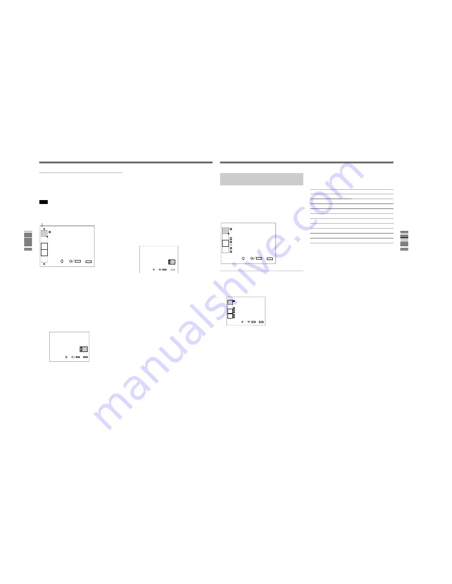
Using the MENU
Expert mode indication
To exit from the expert mode
When you press the ON/STANDBY key after the
adjustment in the expert mode, the projector is set to
the standby mode and the menu mode is returned to
the user or pro-user mode automatically.
To reset to the service mode before setting the
projector to the standby mode, do the following:
1
Press the NORMAL key.
2
Press the keys in the following order:
ENTER
n
ENTER
n
B
n
b
n
ENTER
Be sure to press the keys one after another within 2
seconds.
The following display appears.
D o y o u w i s h t o r e t u r n
t o t h e S E R V I C E
C O N T R O L M O D E ?
Y E S
N O
SEL:
SET:
ENTER
EXIT: NORMAL
3
Press the
v
or
V
key to select YES, then press the
ENTER key. The service mode is set.
If you select NO, the display disappears leaving
the expert mode.
Expert mode (E)
This is the menu mode for the expert service personnel
who have specialized technology and knowledge on
the projector.
Note
Normally do not use this mode. An inappropriate
operation in this mode may degrade the performance
of the projector.
I N P U T - A
D E V I C E C O N T R O L
SEL:
SET:
ENTER
EXIT: MENU
SERVICE
SETTING3
PIC
ORBITING
INT.OSC
SETTING
TIMER
UNI
FORMITY
E
To set to the expert mode
1
Set the projector to the service mode.
For details, see “To set to the service mode” on page
53.
2
Press the NORMAL key.
3
Press the keys in the following order:
ENTER
n
ENTER
n
B
n
b
n
ENTER
Be sure to press the keys one after another within 2
seconds.
The following display appears.
D o y o u w i s h t o e n t e r
i n t o t h e E X P E R T
C O N T R O L M O D E ?
Y E S
N O
SEL:
SET:
ENTER
EXIT:
MENU
4
Press the
v
or
V
key to select YES, then press the
ENTER key.
If you select NO, the display disappears without
changing the menu mode.
5
Press the MENU key.
The menu in the expert mode appears with the
letter “E” at the top-left of the screen.
Before adjustment
55
Before adjustment
The PIC CTRL (Picture Control)
Menu
(User/Pro-user/Service/Expert modes)
The PIC CTRL menu displays the information on the
picture adjustments. To adjust the picture, use the keys
on the remote commander.
Items that can be adjusted are highlighted in green.
You cannot select the items indicated in white.
V I D E O
V I D E O M E M O R Y
N o . 1 0
1 6 : 9 N T S C S I G N A L
C O N T R A S T 8 0
B R I G H T 5 0
C O L O R 5 0
H U E 5 0
S H A R P 5 0
PIC
CTRL
SET
SETTING1
SET
SETTING2
INPUT
INFO.
SEL:
SET:
ENTER
EXIT: MENU
VIDEO MEMORY
Indicates the number of video memory.
The number 1 to 10 can be selected with the VIDEO
MEMORY keys on the remote commander.
V I D E O
V I D E O M E M O R Y
N o . 1 0
1 6 : 9 N T S C S I G N A L
C O N T R A S T 8 0
B R I G H T 5 0
C O L O R 5 0
H U E 5 0
S H A R P 5 0
PIC
CTRL
SET
SETTING1
SET
SETTING2
INPUT
INFO.
SEL:
SET:
ENTER
EXIT: MENU
The video memory is a part of the SET MEMORY,
and stores 10 types of the aspect ratio, picture quality,
etc.
Select a video memory number 1 to 10, then the
aspect ratio and picture quality that you adjust will be
stored in the selected video memory.
If you want to use the aspect ratio and picture quality
data stored in the INPUT MEMORY, select OFF.
Contents of the video memory data
COLOR TEMPERATURE, D. PICTURE, V SHIFT
WIDE/NARROW, COMPONENT FORMAT, COMB
FILTER DRC LEVEL, CONTRAST, BRIGHT,
COLOR, HUE, SHARP, RGB SIZE, RGB SHIFT,
BLANKING
For details, see “Video Memory” on page 137.
Aspect ratios preset at the factory
The data for the following aspect ratios have been
stored in each video memory number at the factory.
No.
Aspect ratio
1
4 : 3
2
4 : 3
3
4 : 3
4
4 : 3
5
4 : 3
6
16 : 9
7
16 : 9
8
16 : 9
9
16 : 9
10
16 : 9
Summary of Contents for VPH-G90E
Page 10: ......
Page 120: ......
Page 122: ...2 2 VPH G90E G90U G90M 2 1 3 Location 3 ME MB MC PB M L MA BA F BC NA BB ...
Page 190: ......
Page 204: ......
Page 210: ......
Page 224: ......
Page 337: ...9 1 9 1 VPH G90E G90U G90M SECTION 9 BLOCK DIAGRAMS ...
Page 363: ...2 3 4 5 A B C D E F G H 1 10 1 10 1 VPH G90J G90E G90U G90M SECTION 10 DIAGRAMS ...
Page 437: ...2 3 4 5 A B C D E F G H 1 10 75 10 75 VPH G90J G90E G90U G90M ...
Page 474: ...2 3 4 5 A B C D E F G H 1 10 112 10 112 VPH G90J G90E G90U G90M ...


