1-45
VPH-G90E/G90U/G90M
28
Connections
Connections
3
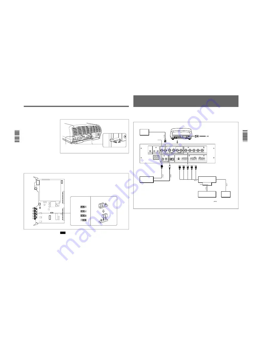
Open the card pullers and pull out the BA and BB boards carefully. Be
careful not to pull the wires.
4
Switch the CN347, CN348 and CN349 connectors on the BA board.
75
Ω
(pin position 3) is selected at the factory.
Set to OPEN (pin position 1) when the input signal is distributed into
other equipment using a branch connector and is terminated at 75 ohms
on that equipment.
Note
The pin position of the CN350 connector is set at the factory as illustrated.
Do not change the setting.
5
Perform the steps
1
to
3
above in the reverse order to replace the BA
and BB boards.
BA board
Pin positions set at
the factory
How to switch the connector
BA and BB
boards
CN347
3 2 1
CN348
3 2 1
CN349
3 2 1
CN350
3 2 1
3
2
1
3
2
1
Switching the 75-ohm Terminate Connectors
Connections
29
Connections
TRIGGER
LINK
S VIDEO
OUT
IN
C IN
Y IN
VIDEO
VIDEO
R-Y/P
R
R
B-Y/P
B
G
B
SYNC/HD
VD
INPUT A
Y
CONTROL S
PLUG IN POWER
DEVICE INDEX
IN
OUT
IN
OUT
IN
OUT
REMOTE
RS-232C/422A
RS-232C RS-422A
IN
OUT
PJ COM
This is an example to connect pieces of video equipment directly to a
single projector.
Use the IFU-1271/1271M Signal Interface Unit.
Setting up
• Set INPUT A in the SET SETTING 1 menu (page 62) to RGB.
• Select VIDEO or S VIDEO by pressing the INPUT SELECT keys on the
remote commander.
• Switch the 75-ohm terminate connectors on the BA board according to
the connections of the computer and color monitor.
For details, see “Switching the 75-ohm Terminate Connectors” on page 27.
Connecting Directly to the Projector
Color
monitor
to video input
Rear
AC power cord (supplied)
to a wall outlet
Video equipment
to video output
to S video output
IFU-1271/1271M
Signal Interface Unit
IFB-12/12A
signal interface
board, etc.
to RGB input
to RGB output
Computer
to RGB output
to RGB input
Color
monitor
Signal flow
R
G
B
SYNC/HD
VD
VIDEO
OUT
AC IN
VIDEO IN
S VIDEO
IN
INPUT A
*
*
For the VPH-G90E model:
IFB-G90E Video Interface Board (optional).
Summary of Contents for VPH-G90E
Page 10: ......
Page 120: ......
Page 122: ...2 2 VPH G90E G90U G90M 2 1 3 Location 3 ME MB MC PB M L MA BA F BC NA BB ...
Page 190: ......
Page 204: ......
Page 210: ......
Page 224: ......
Page 337: ...9 1 9 1 VPH G90E G90U G90M SECTION 9 BLOCK DIAGRAMS ...
Page 363: ...2 3 4 5 A B C D E F G H 1 10 1 10 1 VPH G90J G90E G90U G90M SECTION 10 DIAGRAMS ...
Page 437: ...2 3 4 5 A B C D E F G H 1 10 75 10 75 VPH G90J G90E G90U G90M ...
Page 474: ...2 3 4 5 A B C D E F G H 1 10 112 10 112 VPH G90J G90E G90U G90M ...


