2-20
VPH-G90E/G90U/G90M
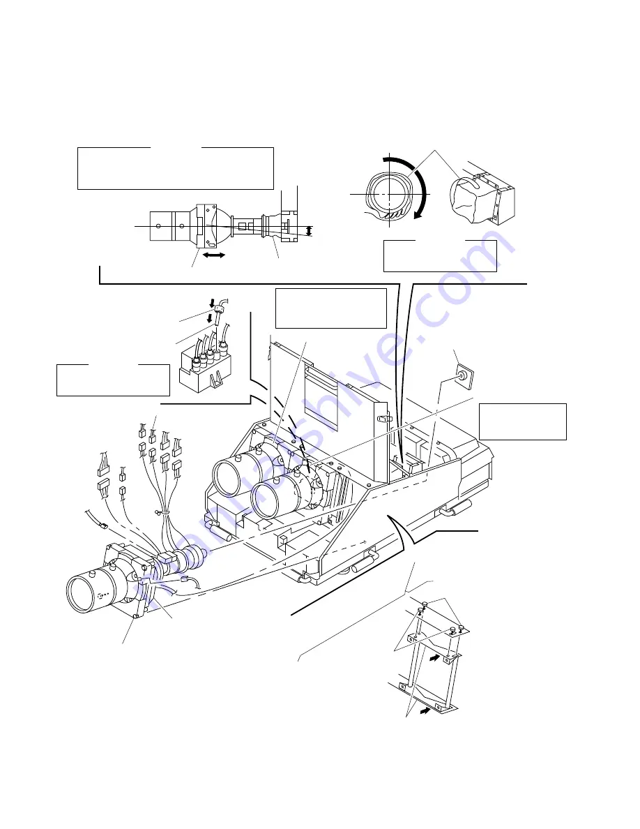
2-2-22. (2) Picture Tube Installation
Shield cover (CB)
[G90E/G90M]
Shield cover (CB)
[G90E/G90M]
Picture tube (B)
Picture tube (G)
Picture tube
Rubber cap
High-voltage cable
5
CBR board
6
Install the high-voltage cable
and rubber cap.
7
Tighten the shield cover (CB).
[G90E/G90M]
4
Four screws
(Hexagon head special screw M5)
3
Picture tube (R)
2
Two stay
Two shafts (B)
1
Loosen the four screws.
8
Tighten the four screws after
adjustment.
Two screws
(SW hexagon head screw
M5
x
12)
4 pin
5 pin
8 pin
9 pin
8 pin
3 pin
GND
GND
[CAUTION]
After installing the picture tubes (B) and (R), move
them in the right and left directions in order to
tighten the shield cover (CB) without being pulled.
[CAUTION]
Check that the high-voltage
cable is firmly installed.
[CAUTION]
Make creases of the shield
cover (CB) at the bottom.
Install the picture tube (B)
in the same manner as the
picture tube (R).
Install the picture
tube (G) in the steps
of
3
to
7
.
Summary of Contents for VPH-G90E
Page 10: ......
Page 120: ......
Page 122: ...2 2 VPH G90E G90U G90M 2 1 3 Location 3 ME MB MC PB M L MA BA F BC NA BB ...
Page 190: ......
Page 204: ......
Page 210: ......
Page 224: ......
Page 337: ...9 1 9 1 VPH G90E G90U G90M SECTION 9 BLOCK DIAGRAMS ...
Page 363: ...2 3 4 5 A B C D E F G H 1 10 1 10 1 VPH G90J G90E G90U G90M SECTION 10 DIAGRAMS ...
Page 437: ...2 3 4 5 A B C D E F G H 1 10 75 10 75 VPH G90J G90E G90U G90M ...
Page 474: ...2 3 4 5 A B C D E F G H 1 10 112 10 112 VPH G90J G90E G90U G90M ...


