PCS-G50/G50P
4-29
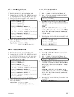
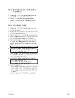
4-3-3. Remote Commander and Operation
Sound Check
1.
Connect the VIDEO IN CAMERA connector of the
unit and the camera, and turn on the power.
2.
Operate the joy stick of the remote commander
towards the camera, and check if sound comes out.
4-3-4. Video Output Check
1.
Connect the VIDEO IN CAMERA connector of the
unit and the camera.
2.
Connect the unit’s RGB OUT and VIDEO OUT AUX
connectors to the color monitor.
3.
Refer to Section 4-1-1, and start the terminal software.
4.
Check that the launcher menu is displayed on the color
monitor connected to the RGB OUT connector.
5.
Enter the following command from the terminal PC,
and check that nothing is displayed (black monitor
display) on the color monitor connected to the RGB
OUT connector.
pcsdb> mail 36, 3a2000000100
↓
6.
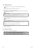
Enter the following command from the terminal PC.
pcsdb> mail 36, 3a3100000200
↓
pcsdb> set b6000014 0
↓
7.
Check that the picture on the color monitor connected
to the VIDEO OUT AUX connector is only the camera
image from the launcher menu.
8.
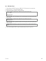
Enter the following command from the terminal PC.
pcsdb> set b6000014 2
↓
pcsdb> mail 36, 3a3100000100
↓
pcsdb> mail 36, 3a2000000200
↓
9.
Check the followings.
.
Color monitor connected to the RGB OUT connector:
Black monitor display
→
Launcher menu displayed
.
Color monitor connected to the VIDEO OUT AUX
connector:
Camera image only
→
Launcher menu displayed
Summary of Contents for Ipels PCS-G50
Page 6: ......
Page 16: ......
Page 26: ......
Page 34: ......
Page 170: ......
Page 186: ......
Page 191: ...PCS G50 G50P 8 7 8 7 CPU 382 B SIDE SUFFIX 12 13 A B C D 1 2 3 4 CPU 382 CPU 382 ...
Page 198: ......
Page 199: ......
Page 200: ...Printed in Japan Sony Corporation 2005 6 22 2005 PCS G50 UC PCS G50P CE E 9 968 181 01 ...


