


PCS-G50/G50P
2-3
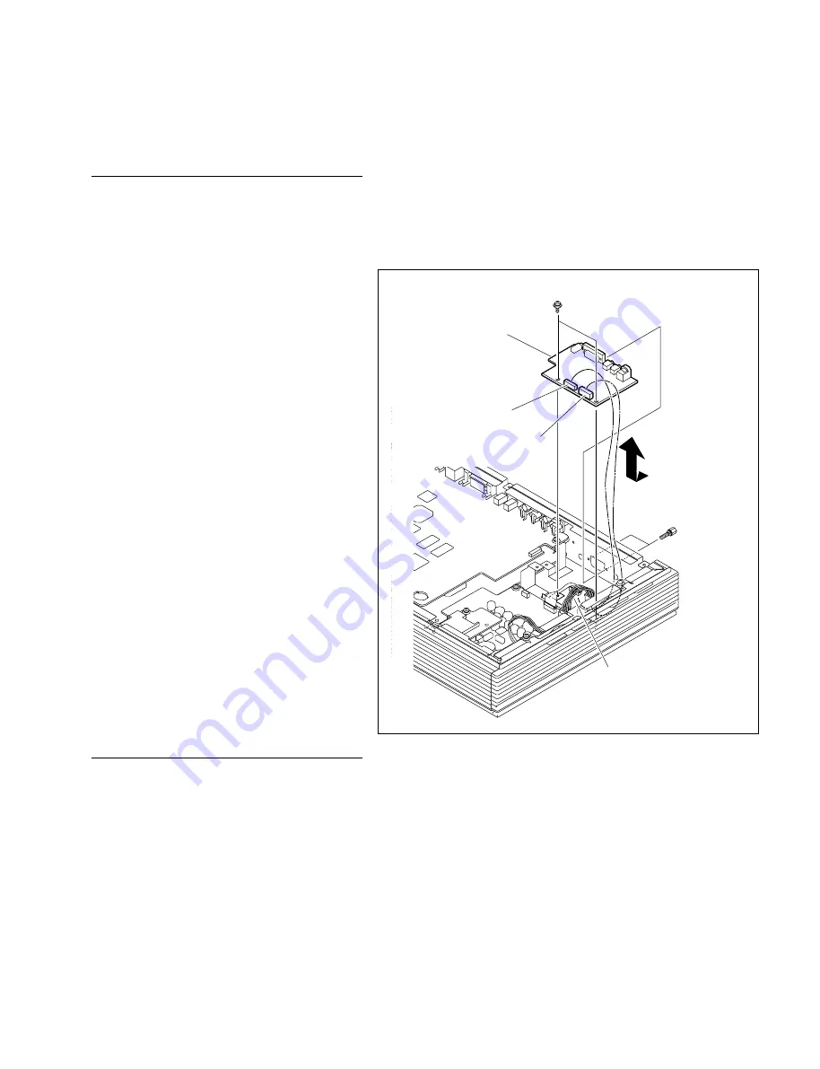
Harness
Connector screws
CN-2635 board
CN707
CN706
PSW3
x
6
2-2. Replacement of Boards
2-2-1. CN-2635 Board
Removal
1.
Remove the top cover assembly.
(Refer to steps 1 to 3 in Section 1-4-1.)
2.
Disconnect the harness from the connectors
(CN706 and CN707) on the CN-2635 board.
3.
Remove the two screws and the two connec-
tor screws, then remove the CN-2635 board
in the direction of the arrow.
Installation
4.
Reinstall the CN-2635 board in the reverse
order of steps 2 and 3.
5.
Reassemble the unit in the reverse order of
step 1.
Summary of Contents for Ipels PCS-G50
Page 6: ......
Page 16: ......
Page 26: ......
Page 34: ......
Page 170: ......
Page 186: ......
Page 191: ...PCS G50 G50P 8 7 8 7 CPU 382 B SIDE SUFFIX 12 13 A B C D 1 2 3 4 CPU 382 CPU 382 ...
Page 198: ......
Page 199: ......
Page 200: ...Printed in Japan Sony Corporation 2005 6 22 2005 PCS G50 UC PCS G50P CE E 9 968 181 01 ...