1-7
VPD-LE100A/LE100E/LE100U
12
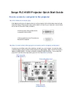
Location and Function of Controls
Rear
1
INPUT A connectors
RGB input connectors (R, G/G SYNC, B, SYNC/
HD, VD) (BNC type): Connect to the video
outputs of equipment such as a computer or a
video camera.
Note
The INPUT A connectors do not function when the
PC-3000 Signal Interface Switcher is connected.
2
Signal interface board attachment part
(INPUT B)
An optional signal interface board can be attached
according to your requirements. If you install the IFB-
12A interface board to this section and select the
output mode, you can output the signal input through
the INPUT A connectors.
For details on installing the interface boards, consult with
qualified Sony personnel.
3
Signal interface board attachment part
(INPUT C)
An optional signal interface board can be attached
according to your requirements.
Note
You cannot select the output mode when attaching the
IFB-12A interface board.
0
0
CONTOROL S
IN
PLIG IN POWER
STATUS/ERROR MESSAGE
OUT
STANDBY
1
ON
@
RS-
232C
RS-
422A
RS-232C/422A
PJ COM
IN
R
G/G SYNC
SYNC/HD
VD
B
OUT
TRIG
DEVICE INDEX
CONTOROL
6
7
8
9
0
qa
qs qd
qf
5
4
3
1
2
4
IFB-LE100 interface board attachment part
(INPUT D)
The optional IFB-LE100 interface board can be
attached.
5
Rear remote control (SIRCS) detector
6
ON indicator
Lights when the power is turned on.
The indicator flashes for about 15 minutes after the
power is turned off by pressing the STANDBY key, as
the fan runs to cool down the inside of the projector.
7
STANDBY
1
indicator
Lights to indicate that the projector is in standby mode.
8
STATUS/ERROR MESSAGE (message) display
window
Displays the signal status and error messages about the
input signals.
9
Lamp cover
The lamp is inside.
For the lamp replacement, consult with qualified Sony
personnel.
q;
Carrying handle
Pull up the handle when carrying the projector.
13
Location and Function of Controls
qa
CONTROL S IN/OUT jacks (stereo minijack)
Connect to the control S jacks of other Sony
equipment.
CONTROL S IN/PLUG IN POWER (DC 5 V
output) jack: Connects to the CONTROL S OUT
jack of the supplied Remote Commander when
using as a wired Remote Commander. In this case,
you do not need to install the batteries in the
Remote Commander, since the power is supplied
from this jack.
CONTROL S OUT jack: Outputs the control S
signal.
Note
When connecting the remote commander cable to the
CONTROL S IN jack, the remote control detectors
will not function.
qs
TRIG (trigger output) jack (monaural minijack)
The signal is transmitted from this jack to the
connected equipment whether the projector is on or
off. (This is not a power source for external
equipment.) When the power is on, the TRIG jack
transmits approximately 12 V trigger signal to external
equipment connected to the projector. This signal is
useful when you connect a system integrator, etc., to
the projector; you can pull down an electric screen,
draw an electric curtain, or dim lights at the same time
as you turn on the projector power. (You cannot use
the trigger signal as a power source.)
This jack outputs 0 V DC when the power is off.
qd
DEVICE INDEX switch
Set the device index number of the projector when
using multiple projectors. You can set the numbers
between “01” and “99.” It is set to “01” at the factory.
You can also set the group index number in the menu
for system setup.
Note
Do not set the device index number to “00.”
If you do, the projector will not operate with the
Remote Commander.
You can operate the projector with the keys on the
control panel of the projector but the connected
equipment cannot be operated with the keys on the
control panel.
qf
REMOTE connectors
Used to expand system capability.
RS-232C/RS-422A select switch: Selects according
to the interface connected to the RS-232C/422A
connector.
RS-232C/422A connector (D-sub 9-pin, female):
Connect to a computer to operate the projector
from the computer.
PJ COM IN/OUT connectors (D-sub 9-pin,
female): The connectors conform to the RS-485
standards and are used to expand system
capability for Sony projectors.
For details on connections, see the PJ COM protocol
manual for Sony projectors.
Summary of Contents for IFB-LE100
Page 70: ......
Page 94: ......
Page 114: ......
Page 180: ...9 10 VPD LE100A LE100E LE100U 9 10 2 3 4 5 A B C D E F G H 1 BA BA BA A SIDE SUFFIX 11 ...
Page 181: ...9 11 VPD LE100A LE100E LE100U 9 11 2 3 4 5 1 A B C D E F G H BA BA BA B SIDE SUFFIX 11 ...
Page 199: ...9 29 VPD LE100A LE100E LE100U 9 29 2 3 4 5 1 A B C D E F G H BB B SIDE SUFFIX 11 BB BB ...
Page 229: ...9 59 VPD LE100A LE100E LE100U 9 59 2 3 4 5 1 A B C D E F G H M M M B SIDE SUFFIX 11 ...
Page 238: ...9 68 VPD LE100A LE100E LE100U 9 68 2 3 4 5 A B C D E F G H 1 G A SIDE SUFFIX 11 G G ...
Page 239: ...9 69 VPD LE100A LE100E LE100U 9 69 2 3 4 5 1 A B C D E F G H G B SIDE SUFFIX 11 G G ...
Page 248: ...9 78 VPD LE100A LE100E LE100U 9 78 2 3 4 5 A B C D E F G H 1 BM BM BM A SIDE SUFFIX 11 ...
Page 249: ...9 79 VPD LE100A LE100E LE100U 9 79 2 3 4 5 1 A B C D E F G H BM BM BM B SIDE SUFFIX 11 ...
Page 254: ...9 84 VPD LE100A LE100E LE100U 9 84 2 3 4 5 A B C D E F G H 1 XB XB XB A SIDE SUFFIX 11 ...
Page 255: ...9 85 VPD LE100A LE100E LE100U 9 85 2 3 4 5 1 A B C D E F G H XB XB XB B SIDE SUFFIX 11 ...
Page 258: ......