1-9
CCU-TX7 (E)/V1
17
CT-181
AA-90
YD-26
ES-20
SDI-44
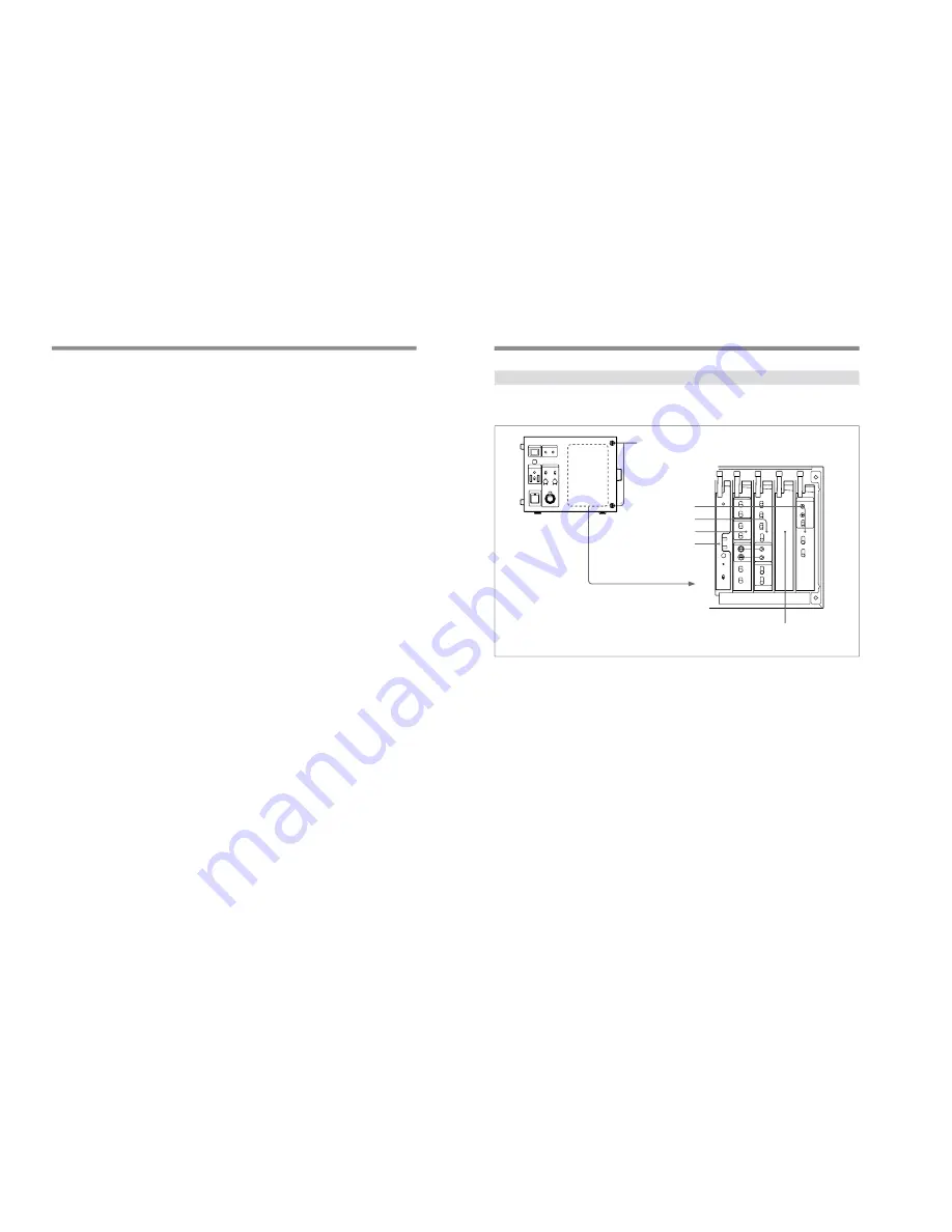
Internal Board Switches and Knobs
Loosen the two screws on the right side of the front
panel to expose switches and knobs on the edges of
internal boards.
For details concerning adjustment of internal board
switches and knobs, contact a Sony dealer.
1
ES-20 board
2
AA-90 board
3
CT-181 board
Front panel screws
YD-26 board
SDI-44 board
(DXBK-701)
a)
a) The SDI-44 board is an option available as the DXBK-701. For details of installation
and operation, refer to the operating instructions supplied with the DXBK-701.
16
Location and Function of Parts
PROMPT VIDEO connectors
Use these connectors to input teleprompter signals.
75-
Ω
termination switches
When only one loop-through connector is used and the
other connector in the pair is not connected to any
external device, set the corresponding 75-
Ω
termination switch to the ON position.
!™
MIC OUT connectors (XLR 3-pin)
Use these connectors to output microphone signals
(CH1 and CH2) from the connected video camera.
!£
DC IN connector (XLR 4-pin)
Use this connector to operate this unit using a DC
power source (10.5 to 17 V).
!¢
SDI (serial digital interface) OUT connectors 1
and 2 (BNC type)
These output the signals from the video camera as SDI
signals. Connect them to a digital VCR, digital video
switcher, video monitor, or other device with an SDI
input connector. Using the SDI OUT connectors
requires the optional DXBK-701 board.
For details, refer to the operating instructions for the
DXBK-701.
!
∞
AC IN connector
Use this connector to connect an AC power source via
the supplied power cord. Use the supplied plug retainer
to attach the power cord to this unit.
!§
Breaker switch
If the input current exceeds 10 A during operation of
the unit on a DC power source, the breaker is actuated
to shut off the power supply. To resume operation,
push in the breaker switch after making sure the input
current does not exceed 10 A.


