background image


UPS for 400 Vac Grid, User Guide, doc. rev. 4 

108  


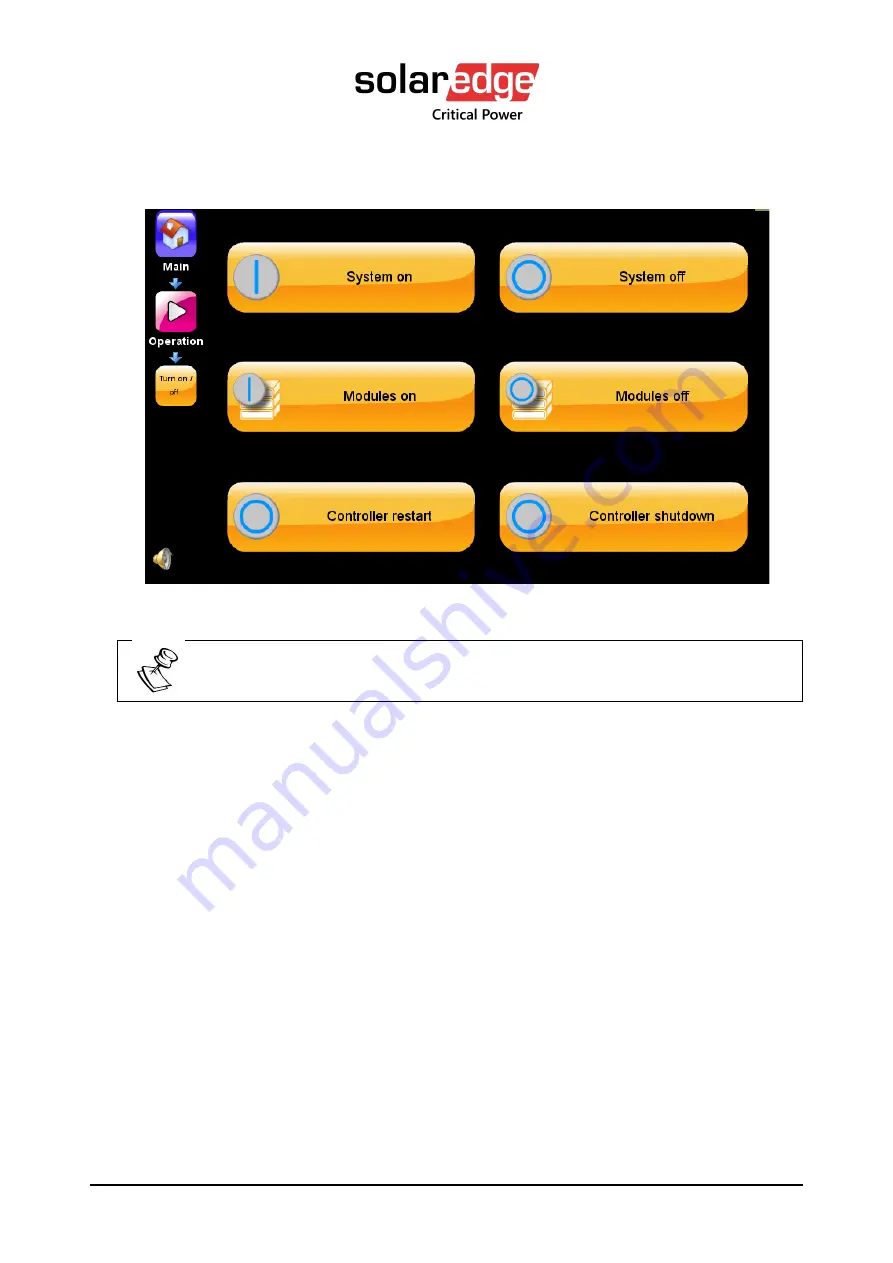
The Turn on/off screen appears: 


Figure 94:  Turn off/on menu  


Pressing the On/Off button on the System menu also brings you to this 
(Operation > Turn on/off) screen (as shown above). 


3.


Select System on

Summary of Contents for Critical Power B300

Page 1: ...THREE PHASE MODULAR UPS FOR THE 400V GRID B300 USER GUIDE Revision 4 April 2021 Doc 2MUM B300U This user guide is for products B300...

Page 2: ...Remember to register your product at https criticalpower solaredge com warranty in order to activate your warranty...

Page 3: ...YPASS MODE 22 5 EMERGENCY POWER OFF EPO MANUAL 23 5 1 POWER OFF BUTTON POB 23 5 2 EPO INDICATION 23 5 3 BATTERY TRIP COIL DRY CONTACT 23 5 4 RESTARTING THE UPS AFTER EPO 24 6 UPS USER INTERFACE 25 6 1...

Page 4: ...8 2 1 6 3 Set last maintenance date 46 8 2 1 6 4 System snapshot 46 8 2 1 6 5 Start logging 46 8 2 2 Setup Modules 46 8 2 2 1 AC input voltage calibration 47 8 2 2 2 AC output voltage calibration 48 8...

Page 5: ...alysis event 72 8 2 4 6 Setup STSW Sync fault delay transfer 73 8 2 5 Setup Alarms 74 8 2 5 1 Setup Alarms Alarms configuration 75 8 2 5 2 Setup Alarms Set limits 76 8 2 5 2 1 Setup Alarms Set Limits...

Page 6: ...ation Switch on off System off 109 8 3 2 Operation Turn on off modules on off 109 8 3 2 1 Operation Turn on off Modules off 109 8 3 2 2 Operation Switch on off Modules On 111 8 3 3 Operation Turn on o...

Page 7: ...Battery Test option 33 Figure 20 ECO mode on 33 Figure 21 ECO mode off option 34 Figure 22 System menu UPS off 35 Figure 23 LCD control panel displays the System menu 37 Figure 24 Navigation trail to...

Page 8: ...5 Figure 62 Setup Alarms Alarms Configuration Restore Factory Settings 76 Figure 63 Alarms Alarm Limits 77 Figure 64 Alarms limit DC voltage limit configuration 77 Figure 65 Alarm limits AC voltage co...

Page 9: ...Test 117 Figure 105 UPS is On but ECO mode is not turned on 118 Figure 106 UPS is on ECO mode is turned on and inverter is in standby state 119 Figure 107 UPS is ON UPS is on and ECO mode Inverter is...

Page 10: ...age option 140 LIST OF TABLES Table 1 Key to Figure 3 17 Table 2 Key to Figure 4 25 Table 3 Description of email parameters 87 Table 4 Alarms that can trigger output dry contacts 98 Table 5 Key to Fig...

Page 11: ...mages are only illustrative and are not intended to match the readings on a specific system in any particular environment Operation and control of the UPS is accomplished through a touch sensitive LCD...

Page 12: ...injury to personnel or even death Ensure all power is disconnected before performing installation or maintenance See installation guide for recommended clearances The UPS must be well grounded to the...

Page 13: ...d between the battery and the UPS for example the Ferraz Shawmut A70QS fuse WARNING RISK OF LETHAL ELECTRIC SHOCK WARNING HIGH TOUCH CURRENT EARTH CONNECTION ESSENTIAL BEFORE CONNECTING SUPPLY WARNING...

Page 14: ...battery circuit and AC circuit breakers are turned OFF Do not turn ON the battery circuit breaker when the battery cabinet is disconnected from the UPS Do not install the UPS next to gas or electrical...

Page 15: ...urges spikes and sags are inherent in commercial utility power Over time these irregularities shorten the life of equipment and components The UPS continually eliminates power irregularities thus help...

Page 16: ...have a maximum power capacity of 300kVA The UPS includes from one to ten UPS power modules each supplying 30 kVA In addition to the power modules the UPS includes 1 A system controller 2 A static swit...

Page 17: ...Vac Grid User Guide doc rev 4 C Static switch D Dry contacts E Circuit breakers F Batteries Figure 2 Connection Terminals perspective view Figure 3 B300 model Connection terminals rear view Table 1 K...

Page 18: ...4 18 ITEM DESCRIPTION A Protective earth ground bus bar B Neutral and midpoint terminals C AC RECTIFIER INPUT terminals L1 L2 L3 D BYPASS INPUT terminals L1 L2 L3 E AC OUTPUT terminals L1 L2 L3 F BATT...

Page 19: ...s the LCD control panel used to monitor and operate the UPS 3 2 UPS module 30 kVA 30 kW The power module is the core of the UPS which consists of from one to ten identical internal modules operating i...

Page 20: ...cting fuses semiconductor fuses must be used between the battery and the UPS Protect the batteries from moisture dampness and foreign substances A safe disconnect device must be used on each battery b...

Page 21: ...ery mode is used whenever the grid power is faulty The duration of the battery operation is determined by the load demand and the battery capacity 4 3 Bypass mode During bypass operation the load rece...

Page 22: ...power engineer needs to perform maintenance on the UPS but does not want to risk the possibility of disturbing or unintentionally disconnecting the load The Maintenance Bypass function routes the load...

Page 23: ...mb vented front door WARNING POB IS NOT EPO AND CANNOT BE USED IN EMERGENCIES 5 2 EPO indication Any of the output dry contacts can be assigned to indicate when the EPO switch has been activated The o...

Page 24: ...e restarted as follows 1 Reset the EPO switch 2 Switch OFF the following circuit breakers Ac input Bypass input Battery 3 Wait 1 minute then switch on the AC input and bypass input circuit breakers 4...

Page 25: ...trates the System menu and Table 2 explains the System menu s features Table 2 Key to Figure 4 ITEM DESCRIPTION 1 The operational status ON OFF and current mode Normal inverter mode bypass mode Batter...

Page 26: ...dicates the status of the battery charging or discharging Pressing this icon displays the Battery Status screen 8 Load indicators Indicates the approximate load level of each output phase as a percent...

Page 27: ...ion from the System menu is used to turn the UPS on or off or transferring the load to bypass Figure 5 Operation option Refer to Section 8 3 for a full description of all of the Operation menu functio...

Page 28: ...ated Selecting the component will provide more detailed information about the problem Clicking on the various parts of the diagram reveals more detailed information including present voltage and curre...

Page 29: ...tion of all Setup menu functions see Section 8 2 6 2 3 1 Time Select on the Time icon on the System menu to see the system time the time zone setting relates to when daylight savings time goes into ef...

Page 30: ...dry contacts can be used to trigger external devices Refer to Section 8 2 9 for details 6 2 4 Profile menu Selecting the Profile icon from the System menu lets you view various system parameters as de...

Page 31: ...power down and the start and end of all alarm conditions For a full description of the Log option see Section 8 6 6 3 Operating the UPS From the System menu the Operation option is used to perform th...

Page 32: ...de doc rev 4 32 Figure 13 Turn on UPS option 6 3 2 Turn off UPS Figure 14 Turn off UPS option 6 3 3 Turn off power modules Figure 15 Turn off power modules option 6 3 4 Turn on power modules Figure 16...

Page 33: ...4 6 3 5 Transfer load to bypass Figure 17 Transfer load to bypass option 6 3 6 Transfer load to inverter Figure 18 Transfer load to inverter option 6 3 7 Battery test Figure 19 Battery Test option 6...

Page 34: ...UPS for 400 Vac Grid User Guide doc rev 4 34 6 3 9 Turn off ECO Mode Figure 21 ECO mode off option...

Page 35: ...ly shutdown i e UPS state is OFF The shutdown was performed manually indicated by the UPS shutdown by OFF button and no output message The load icon bottom right hand corner of the screen indicates th...

Page 36: ...a problem with the rectifier voltage You can see the input voltage readings on the status screen If the readings are not within acceptable limits verify that the external circuit breaker for the recti...

Page 37: ...nel is touch sensitive The user navigates through system screens by lightly pressing different system icons Figure 23 LCD control panel displays the System menu The current navigation path i e breadcr...

Page 38: ...mode The display unit is mounted on a holder and can be removed from the holder if necessary In the example shown above Figure 24 the user began navigation on the System menu screen then chose Setup a...

Page 39: ...ser interface you may notice that on certain sub menus some of the functions are marked with a little key shaped icon see Figure 26 Figure 26 Key icon on Email Configuration These functions may requir...

Page 40: ...submenu is used to update the UPS about its operating environment with regard to the following parameters Nominal input and output values of the UPS Total number of modules and how many of them are re...

Page 41: ...Hz or 60 Hz Before modifying the UPS nominal frequency the UPS must be turned off by means of the ON OFF button on the System menu screen Obviously the nominal system frequency chosen should be the sa...

Page 42: ...em inverter load capacity 8 2 1 2 1 Redundancy Redundant modules are those in excess of the minimum number of modules required to supply the maximum expected UPS load Each UPS module can supply 30 kVA...

Page 43: ...nt 8 2 1 3 3 ECO mode In ECO mode also called standby mode under normal conditions the load is powered from the bypass line In the event of a problem with the bypass input the load is transferred to t...

Page 44: ...and STSW not the battery 2 With the input switch open OFF and the bypass switch closed ON test the Inverter STSW and the battery In both options the load is not powered by the Inverter Should self lo...

Page 45: ...turn itself back on when the AC mains power returns following a prolonged power failure or if it should remain off 8 2 1 5 Setup System Controller This submenu contains functions related to the system...

Page 46: ...tistical snapshot of system parameters and measurements and saves it to a flash drive Before taking the snapshot insert a writable flash drive into one of the USB ports on the front right of the syste...

Page 47: ...nu hierarchy Figure 31 Setup Modules menu options Disable Auto Correction before making any changes covered in this Section 8 2 2 1 AC input voltage calibration Use this function if it becomes necessa...

Page 48: ...gs of any of the UPS s input phases This calibration should be performed on each module one module at a time until all modules have been calibrated The value you enter is sent to all modules so input...

Page 49: ...voltage phases are calibrated before the UPS leaves the factory but over time or due to environmental factors the UPS s output voltage may drift slightly Each AC power module s output voltage must be...

Page 50: ...er and open the rear bottom cover to expose the output and mid point bus bars 3 Turn on input AC and battery circuit breakers 4 Turn on the system and wait for it to transfer to normal mode 5 Select a...

Page 51: ...e 32 Output terminals You would expect the value to be around 230VAC 3 V 15 Compare your measured value to the nominal output voltage 16 Adjust line 2 up or down accordingly to acquire the desired out...

Page 52: ...allowed 8 2 2 8 DC voltage adjustment This function is used to correct any inaccuracy in each module s measurement of its internal DC voltage The UPS s re adings are calibrated before the UPS leaves t...

Page 53: ...ault and should not be changed 8 2 2 10 Auto correction When the average output voltage of the UPS modules is above or below what it should be the controller performs Auto Correction which consists of...

Page 54: ...alibrations or adjustments the Auto Correction feature should be re enabled for optimal system performance 8 2 2 11 Power walk in At system startup this parameter give you control of the time it takes...

Page 55: ...3 Setup Battery For complete instructions contact your service provider The following sections are for technician use only and should only be performed by trained professionals familiar with the syst...

Page 56: ...ons The UPS supports the use of standard lead acid batteries and also lithium ion batteries If you plan to use lithium ion batteries consult with your dealer to be sure that the battery setup paramete...

Page 57: ...57 UPS for 400 Vac Grid User Guide doc rev 4 Figure 38 Setup Battery menu hierarchy 8 2 3 1 Setup Battery Battery test parameters The parameters in this section relate to the battery test function...

Page 58: ...er Guide doc rev 4 58 Figure 39 Battery Battery Test menu options 8 2 3 1 1 Battery test fault voltage When this voltage is reached during a battery test the battery has failed the test Figure 40 Batt...

Page 59: ...alue to which the rectifier s output voltage descends during a battery test Figure 41 Rectifier voltage at Battery Test 8 2 3 1 3 Automatic battery test interval The UPS conducts a periodic battery te...

Page 60: ...t yet been charged from the mains for eight consecutive hours since its last significant discharge the test is postponed until the battery is fully charged 8 2 3 1 4 Maximum duration of battery test S...

Page 61: ...Figure 44 Setup Battery Battery Current 8 2 3 2 1 Enable Disable current sensors Use this function to enable or disable the battery current sensors The UPS has a built in internal current sensor Figu...

Page 62: ...re two options Set maximum battery charging rate to 0 1 x battery capacity Set maximum battery charging rate to 0 2 x battery capacity 8 2 3 2 3 Minimum DC voltage at current limit Use this function t...

Page 63: ...2 3 3 Setup Battery end of backup voltage limit During a mains power blackout the batteries provide power to the UPS s inverter In the process the battery voltage continually decreases The End of bac...

Page 64: ...per battery block The UPS computes the average voltage per battery block based on 60 cells 8 2 3 4 Setup Battery Battery low limit voltage When the battery reaches a low voltage due to discharge an al...

Page 65: ...e the duration of the battery test If you do not know your battery capacity look at one of the battery cells The Ah rating of a battery cell is usually indicated on the outside of the cell This same n...

Page 66: ...User Guide doc rev 4 66 Figure 51 Battery Battery Temperature Control Select Temperature compensation parameters The Temperature Compensation Parameters screen appears Figure 52 Battery Temperature co...

Page 67: ...to be used when battery temperature compensation is enabled 8 2 3 7 LVD battery protector In the event of a mains power outage the battery supplies power to the load through the inverter The battery...

Page 68: ...Figure 53 Battery LVD battery protector 8 2 4 Setup STSW For complete instructions contact your service provider The following sections are for technician use only and should only be performed by tra...

Page 69: ...69 UPS for 400 Vac Grid User Guide doc rev 4 Figure 54 Static Switch menu options Figure 55 Setup Static Switch options...

Page 70: ...calibrations are not allowed 8 2 4 2 Setup STSW Calibrate output voltage Caution For calibration refer to SolarEdge Customer Service Field calibrations are not allowed 8 2 4 3 Setup STSW High level se...

Page 71: ...Setup STSW Hi level setup STSW integration time This option controls the amount of time the static switch waits before transferring the load to bypass after detecting that the inverter output voltage...

Page 72: ...bypass in a situation where the UPS is operating under near overload conditions The factory default setting of 85 is recommended for most environments 8 2 4 5 Setup STSW Enable disable analysis event...

Page 73: ...Grid User Guide doc rev 4 Figure 58 Static Switch Enable Disable Analysis Event It is for use by a technician when troubleshooting 8 2 4 6 Setup STSW Sync fault delay transfer Figure 59 STSW Sync fau...

Page 74: ...after half wave If you select the Full cycle checkbox transfer will happen after full wave If you select the None checkbox transfer to bypass will be disabled 8 2 5 Setup Alarms For complete instructi...

Page 75: ...Factory default settings are already assigned to each alarm message when you install the UPS It may be however that in your site a particular alarm condition is more or less important that the defaul...

Page 76: ...checkbox the selected alarm will be ignored all together If you select the For log only checkbox the selected alarm will only be added to the log file You can change the default alarm priority of a s...

Page 77: ...Alarm Limits 8 2 5 2 1 Setup Alarms Set Limits DC limits Use this function to set the voltage levels at which the DC VOLTAGE HIGH and DC VOLTAGE LOW will be activated Figure 64 Alarms limit DC voltag...

Page 78: ...e causes an AC voltage alarm to turn on and off many times rapidly The hysteresis value is the number of volts that a measurement must change before an alarm senses that the measurement has changed So...

Page 79: ...79 UPS for 400 Vac Grid User Guide doc rev 4 Figure 66 Alarms limit temperature configuration...

Page 80: ...nal Setup Connectivity Network configuration The UPS can be monitored from a distance over an intranet or the Internet through the same menus and screens used on the UPS control panel This feature is...

Page 81: ...tem can be performed using the web interface 8 2 6 2 Network configuration options 8 2 6 2 1 Network configuration Obtain IP address automatically This is the right choice if your computer network sup...

Page 82: ...or 400 Vac Grid User Guide doc rev 4 82 The SNMP screen appears Figure 68 Setup Connectivity SNMP configuration options 6 Select Add new host The NEW SNMP host screen appears Figure 69 Creating a new...

Page 83: ...Select one of the ports from the list If your system includes this option the serial communication connector is labeled RS232 and is located on the left side of the dry contact panel of the UPS Figure...

Page 84: ...er numbers shown in Table 7 The registers in Table 7 can be addressed either as holding registers for example 4x0001 or as input registers for example 3x0001 8 2 6 5 1 Defining a TCP Modbus link Enter...

Page 85: ...tarting and ending of system alarms The message body contains A timestamp The user assigned priority of the message Informational Warning Critical The main message text as it appears in the log The st...

Page 86: ...UPS for 400 Vac Grid User Guide doc rev 4 86 Figure 73 The email configuration menu 2 Configure the parameters as explained in the following table...

Page 87: ...sending email address You are prompted for the email address and its password Enable TLS Enable the TLS encryption protocol for the outgoing emails SENDER EMAIL ADDRESS This address will appear in the...

Page 88: ...ecipient To add a new email recipient 1 Selecting the Email recipients button brings up a list of the existing recipients and the opportunity to add a new recipient 2 Select Add new recipient Figure 7...

Page 89: ...text input field The Is Active checkbox is selected by default to indicate that the recipient is active and should be sent email 6 If you do not want the recipient to receive an email uncheck the Is A...

Page 90: ...larms button on email recipient screen 9 After the recipient has been created the Alarms button in the lower left of the screen becomes active If you select the Alarms button the following screen appe...

Page 91: ...iate alarm checkbox 10 Select Confirm The appropriate alarm is sent to the recipient when the UPS alarm is triggered 8 2 6 7 Controller host name Use this option to specify a name for the controller T...

Page 92: ...es those features related to time as follows Figure 79 Setup Time options 8 2 7 1 Adjust date time Enter the year month day hour minute and second 8 2 7 2 Setup Time Adjust date time To adjust date ti...

Page 93: ...per time zone 8 2 7 4 Setup Time Time Synchronization This will only work when connected to a network Figure 81 Setup Time Time Synchronization 8 2 7 5 Setup Time Set last maintenance date This functi...

Page 94: ...PS is connected to a computer network this information can be seen by someone who is monitoring the UPSs via an SNMP program This information is not seen or used by the network manager For ID informat...

Page 95: ...cts This function enables the user to manage the UPS s input and output dry contacts Figure 83 Setup Dry Contacts menu A password may be required to use the sub functions on this menu If you do not ha...

Page 96: ...auxiliary contacts which close when the circuit breaker closes and open when the circuit breaker opens these auxiliary contacts on the battery circuit breaker can be connected to one of the pairs of...

Page 97: ...cting the Enabled box for that dry contact in the same screen see Figure 85 An alarm has been pre assigned to each of the input dry contacts You can see these alarms in the Setup Alarms function They...

Page 98: ...ut dry contact will change Any number of output dry contacts can be linked to a single alarm condition Each output dry contact can be linked to any number of alarm conditions The output dry contacts a...

Page 99: ...defined Emergency Power off is active End of battery backup battery discharged to shutdown limit Fan failure High load level Load is now running on bypass Low battery voltage More than one module is...

Page 100: ...odule 6 is sending an alarm or warning UPS module 7 is sending an alarm or warning UPS module 8 is sending an alarm or warning UPS module 9 is sending an alarm or warning UPS module 10 is sending an a...

Page 101: ...e alarm conditions in Table 4 the output dry contact s associated with that alarm if any generates a message to the log file A system snapshot is also saved to the log file When the alarm condition ce...

Page 102: ...tion This informs the UPS that the generator is providing the input power and the batteries should not be charged Setting the normal state of the input dry contact normally open or normally closed is...

Page 103: ...es to active status the factory default settings of the UPS Performing this function does not have any effect on what is saved by the SAVE SETTINGS function above The Restore Factory Settings function...

Page 104: ...erface 8 2 11 1 Setup Authorization Set user authorization level There are three Security levels User Technician Super User The Technician and Super User levels have access to additional capabilities...

Page 105: ...ization Operations Authorization This allows the technician to limit the operational access to the UPS Operational changed like Turning on and off Transferring the load Battery tests Can be changed to...

Page 106: ...UPS for 400 Vac Grid User Guide doc rev 4 106 8 3 Operation menu Figure 92 The Operation option on the System menu...

Page 107: ...he UPS on off 8 3 1 1 Operation Turn on off System on This section explains how to turn the UPS on following normal shutdown To turn the UPS on 1 Verify that the input and battery circuit breakers are...

Page 108: ...id User Guide doc rev 4 108 The Turn on off screen appears Figure 94 Turn off on menu Pressing the On Off button on the System menu also brings you to this Operation Turn on off screen as shown above...

Page 109: ...the internal DC voltage up to 405 V after which it is ready to supply power to the load 8 3 1 2 Operation Switch on off System off To turn the UPS off 1 From the System menu select Operation Turn on...

Page 110: ...power modules cannot support the remaining load the load will automatically be transferred to bypass if you confirm To turn power modules off 1 From the System menu select Operation Turn on off Module...

Page 111: ...e this to turn power modules on After a short wait the load is automatically transferred to the inverter This function reverses a power modules off command To turn modules on 1 From the System menu se...

Page 112: ...s Status Modules Locate the PFC and Inverter status 8 3 3 Operation Turn on off Controller restart Shutdown 8 3 3 1 Operation Turn on off Controller restart Restarts the controller The load is unaffec...

Page 113: ...Figure 99 Switch on off Controller Shutdown To reset the system controller there is a recessed Reset button available on the back of the controller panel adjacent to the USB ports Figure 100 Controll...

Page 114: ...load to the modules Modules cannot support load 8 3 4 2 Operation Transfer load Transfer load to bypass Transfers the load from the inverter voltage to the bypass voltage During normal operation the l...

Page 115: ...n also be accomplished manually To transfer the load from inverter voltage to bypass voltage 1 From the System menu select Operation Transfer load Transfer load to bypass The Transfer load to Bypass c...

Page 116: ...al UPS The advantage of operating a UPS in ECO mode is that in effect the UPS operates as a stand by UPS not making use of the rectifier and the inverter most of the time aside from possibly charging...

Page 117: ...pe ECO mode and then enter the password for ECO mode 3 Select Enabled Figure 104 Operation Battery Test If you don t intend to use Analyze Grid mode the Custom Reliability settings take on the meaning...

Page 118: ...te for your environment To transfer the UPS to ECO mode 1 From the System menu select Status and insure the UPS is normal mode The Status screen appears Figure 105 UPS is On but ECO mode is not turned...

Page 119: ...er is in standby state Notice the Status screen when the UPS is ON and ECO mode is ON while the UPS is in standby mode Notice that the yellow line representing the direction of power to the load is tr...

Page 120: ...inverter while there is problem with the grid 8 3 7 Operation UPS software upgrade The software upgrade function allows a service technician to upgrade the various subsystems software Software upgrad...

Page 121: ...v 4 To perform a software upgrade Navigate to Operation UPS software Upgrade If the system is on the following warning screen will appear Figure 108 Required system off prompt Select OK to continue Tu...

Page 122: ...screen appear Figure 109 Select unit for upgrade Select from one of the subsystems to upgrade exclusively If you intend on updating all of the subsystems you can do so by selecting System You will be...

Page 123: ...400 Vac Grid User Guide doc rev 4 Figure 110 Insert USB screen The USB drive can be inserted into any of the three available USB slots located on the side of the system controller Figure 111 USB port...

Page 124: ...de the static switch only a Select STSW see Figure 109 b Press Start to begin the software upgrade process c Wait as the system upgrades the static switch with the relevant software To upgrade the inv...

Page 125: ...position in the rack Figure 113 PFC upgrade screen Press Start to begin the software upgrade process 8 4 Status menu Selecting the Status option from the System menu displays a screen which summarize...

Page 126: ...problem Clicking various parts of the Status screen diagram reveals additional information including present voltages and current readings The Status screen shows the power source and destination rou...

Page 127: ...and nominal values 7 Modules alarm icon When present indicates that there is an active alarm condition for one or more of the UPS modules To see the modules status in detail press the modules icon an...

Page 128: ...O mode This graphic is displayed when using self loading mode or PQ mode Pressing the static switch icon displays the static switch detail screen 11 Voltage and amperage readings of the static switch...

Page 129: ...parameters of various parts of the system Figure 116 System menu Profile options 8 5 1 Profile System Figure 117 Profile System Lists the current values for a number of basic system settings including...

Page 130: ...alues for a number of important battery parameters including Nominal charger voltage Current limit enabled disabled Battery low limit voltage Current limit values in amps Rectifier voltage at battery...

Page 131: ...values for several parameters related to the static switch including Bypass forced or controlled Control by PC activity status active inactive Control by panel activity status active inactive Voltage...

Page 132: ...values mostly alarm limit values for alarms including Dc voltage high limit Dc voltage low limit Ac voltage high limit Ac voltage low limit Over temperature limit Under temperature limit Ac voltage h...

Page 133: ...ication Figure 121 Profile Identification Lists several identifiers Manufacturer Location Model name Attached devices Software version System serial number Identification Contact name Module 1 Module...

Page 134: ...ldest messages so that the log file always contains the latest log events Every log message has a severity level assigned to it There are four different severity levels as described in Table 6 Table 6...

Page 135: ...our finger up or down along the touch screen or use the UP and Down arrow keys To display detailed information about the system status at the time the log entry was recorded tap the log message in que...

Page 136: ...ed display You can navigate to the detailed readings for the previous or the next log message by tapping on the left and right arrows at the top of the screen To close the detailed reading screen and...

Page 137: ...screen the Alarm button can be seen Figure 125 Alarms display from the Log detail screen Selecting this button displays a list of all alarms that were active at the time the log record was viewed Thi...

Page 138: ...PS s connection to the computer network the UPS s IP address and related information This is of relevance if you are using the remote access feature which allows monitoring and control of the UPS from...

Page 139: ...em menu the Time function displays the time on the UPS s internal clock the time zone the current operating time the time since the unit was last turned on and the last recorded maintenance date Figur...

Page 140: ...Guide doc rev 4 140 8 9 Language menu From the System menu the Language function gives you the ability to choose the language in which the display screen option and messages are displayed Figure 130 S...

Page 141: ...141 UPS for 400 Vac Grid User Guide doc rev 4 9 Preventive maintenance Please refer to B300_service_guide_Rev1 1 Preventative maintenance section...

Page 142: ...ble backup time 6 4x0006 Estimated Charge 0 100 Mathematical estimation of battery charge in percent 7 4x0007 Battery Voltage 10 VDC Divide the value by 10 for real measurement 485 10 48 5 VDC 8 4x000...

Page 143: ...2315 10 231 5 VAC 32 4x0032 Output Current Line 2 10 A Divide the value by 10 for real measurement 21 10 2 1 A 34 4x0034 Output Load Line 2 Some units might show values over 100 in case of overload 35...

Page 144: ...of modules As defined by controller settings or the controller license 204 4x0204 Amount of Installed modules As defined by controller settings not the actual responding modules 205 4x0205 Amount of B...

Page 145: ...current units 219 4x0219 Inverter Frequency Line 1 10 Hz Divide the value by 10 for real measurement 502 10 50 2 Hz 220 4x0220 Inverter Voltage Line 1 10 VAC Divide the value by 10 for real measuremen...

Page 146: ...241 4x0241 Charger Current Line 2 10 A Divide the value by 10 for real measurement 21 10 2 1 A 242 4x0242 Charger Power Line 2 10 kW Divide the value by 10 for real measurement 453 10 45 3 KW 243 4x0...

Page 147: ...er Factor Line 2 0 to 100 Divide the value by 100 for real measurement 87 100 0 87 PF 265 4x0265 Output Load Line 2 266 4x0266 Output Voltage Line 3 10 VAC Divide the value by 10 for real measurement...

Page 148: ...ignored or for log only in the controller configuration 302 4x0302 Module 1 Alarm 0 Alarm off 1 Alarm on 303 4x0303 Module 2 Alarm 0 Alarm off 1 Alarm on 304 4x0304 Module 3 Alarm 0 Alarm off 1 Alarm...

Page 149: ...Alarm off 1 Alarm on 331 4x0331 Emergency Power Off Is Active 0 Alarm off 1 Alarm on 332 4x0332 Batteries Failed Last Test 0 Alarm off 1 Alarm on 333 4x0333 AC Input Voltage Low 0 Alarm off 1 Alarm on...

Page 150: ...ponding 0 Alarm off 1 Alarm on 353 4x0353 Controller Adapter Is Not Responding 0 Alarm off 1 Alarm on 354 4x0354 Load Above 90 0 Alarm off 1 Alarm on 355 4x0355 Detected More Modules Then Defined 0 Al...

Page 151: ...iled 0 Alarm off 1 Alarm on Not available on Mega modular UPS since there is no battery in the controller on this model 365 4x0365 Inverter Is Out Of Synchronization With Mains 0 Alarm off 1 Alarm on...

Page 152: ...logies Inc All other trademarks mentioned herein are trademarks of their respective owners Date 05 2019 V2 0 ENG NA Subject to change without notice CHANGE LOG Doc release 1 April 2019 Format Update D...

Reviews: