background image

PCS1 Manual

Page v

Table of Contents

DESCRIPTION

PAGE

Manual Update Record...................................................................................................

 ii

Valuable Coupon.............................................................................................................

 iii

Notice .................................................................................................................................


i v

Table of Contents ...........................................................................................................

 v-vi

SECTION 1: SYSTEM ARRIVAL

S1-1

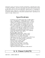
Specifications ...................................................................................................................

 2-3

LIMITED WARRANTY

..................................................................................................


4

Dialog Manual...................................................................................................................


5

CAUTION NOTICES

.....................................................................................................

 6-10

Factory Shipment; Boxes Shipped; Shortage Claim.................................................

 11

Factory Shipment:


Location of Temperature Sensors

.............................................

 11

Factory Shipment: Damaged Equipment; Visible External Damage ....................

 12

PCS1 Shipping Crate: External Damage Inspection..................................................

 13

PCS1 Shipping Crate: Internal Damage Inspection ..................................................

 14

PCS1 Serial Number........................................................................................................

 15

SECTION 2: HEATING DATA

S2-1

PCS1 Solar Theory ............................................................................................................


2

PCS1 Solar Heating...........................................................................................................


3

Empirical Tracking ...........................................................................................................


4

PCS1 Operating Curves..................................................................................................

 5-6

Btus vs GPM Curve..........................................................................................................


7

Btus vs 

D

T Curve..............................................................................................................


7

Pool Heaters .......................................................................................................................


8

Backup heater use.............................................................................................................


8

Solar Panel problems .......................................................................................................


9

Gas Heater problems .......................................................................................................

 10

Heat Pump problems ......................................................................................................

 11

Ventilation........................................................................................................................

 12

SECTION 3:  INSTALLATION

S3-1

Installation Process [Basic]...............................................................................................


2

Suggested Tool Lists .........................................................................................................


3

Suggested Materials..........................................................................................................


4

PCS1 Parts List....................................................................................................................


5

Description of Valves.......................................................................................................


6

STEP ONE: RETROFIT SUPPORT SYSTEM

............................................................................

 7-8

New Layout........................................................................................................................


8

Plumbing Process..............................................................................................................


9

Plumbing Notes ............................................................................................................

 10-13

Summary of Contents for PCS1

Page 1: ...SolarAttic Pool Heater Manual SOLAR Without PANELS Copyright 1988 2002 All Rights Reserved SolarAttic Inc Elk River Minnesota 55330...

Page 2: ...2 27 95 Fixed additional pagination formatting problems on several pages in four sections Note This is the second time and may be related to either the system 7 5 upgrade fixed vs true type scalable f...

Page 3: ...manual from any PCS1 System purchased There is no time limit on this coupon Record your manual purchase here Name ___________________________________________________ Address _________________________...

Page 4: ...ormation and should be used If any doubt exists about complying with building codes the services of a competent and licensed building contractor pool contractor plumber or electrician should be enlist...

Page 5: ...rate External Damage Inspection 13 PCS1 Shipping Crate Internal Damage Inspection 14 PCS1 Serial Number 15 SECTION 2 HEATING DATA S2 1 PCS1 Solar Theory 2 PCS1 Solar Heating 3 Empirical Tracking 4 PCS...

Page 6: ...ption Alternate Wiring Diagram A 40 Pool Pump On Timer Alternate Wiring Diagram B 41 Description Alternate Wiring Diagram B 42 Pump PCS1 On Timer Alternate Wiring Diagram C 43 Description Alternate Wi...

Page 7: ...SECTION 1 SYSTEM ARRIVAL Page S1 1 SECTION ONE SYSTEM ARRIVAL...

Page 8: ...hysically located inside the attic and then transfers this solar radiation from the attic air into the swimming pool s water through a process called forced air convection FULL AUTOMATIC OPERATION Is...

Page 9: ...ominal BTU Rating 60 000 BTUs hour D 32 F I E Pool water input 72 F Attic s Peak 104 F BTU Transfer Range 20 150 000 BTUs per hour Attic space required 3 ft min height to peak and square ft of attic e...

Page 10: ...the purchaser This warranty does not apply to those products which in our judgment have been altered or repaired outside our factory or subjected to misuse negligence accident corrosive atmospheres o...

Page 11: ...step manual where all known installation factors are the same in every instance In such a case the installation manual could then take you from step A to step Z one step at a time Due to the unlimited...

Page 12: ...ll also help prevent damage to equipment swimming pool systems or to the house MAKE SURE YOU READ AND UNDERSTAND ALL OF THESE CAUTION NOTES CHILDREN CAUTION SEVERAL SHARP EDGES ON THE PCS1 CAN CAUSE C...

Page 13: ...URCHASED DAMAGE TO THE VALVES FROM POOR PVC WELDING IS NOT COVERED BY THE MANUFACTURERS WARRANTY ASSEMBLE THE VALVES AND PIPES BEFORE WELDING TO MAKE SURE THEY FIT PROPERLY THIS IS CALLED A PRACTICE R...

Page 14: ...H GRILLE CAUTION THE PROTECTIVE GRILLE HAS SHARP EDGES WHICH CAN CUT YOUR FINGER OR HANDS EXERCISE CAUTION WHEN HANDLING REMOVING OR INSTALLING THIS GRILLE FAN CAUTION DO NOT OPERATE THE PCS1 WITH THE...

Page 15: ...OT REPLACE ANY SELF TAPPING 10 1 2 TEKS SCREW USED ON THE PCS1 REAR COIL SIDE WITH ANY SHEET METAL SCREW GREATER THAN ONE HALF INCH 1 2 IN LENGTH DOING SO CAN DAMAGE THE PCS1 WATER COIL BY PUNCTURING...

Page 16: ...HAVE THESE ATTRIBUTES BUILDING CODE CAUTION INSTALL ALL EQUIPMENT IN ACCORDANCE WITH LOCAL STATE AND NATIONAL CODES TO PREVENT INJURY FATALITIES OR DAMAGE TO EQUIPMENT SERVICE CAUTION UNPLUG THE PCS1...

Page 17: ...c temperature sensors are located inside the LX220 solar controller behind the front panel See page S3 49 drawing Using a phillips screwdriver unlock the front panel door and open the hinged panel Bot...

Page 18: ...OUT OPENING AND INSPECTING THE PARTS AND FIND DAMAGED GOODS INSIDE CALL THE CARRIER UP IMMEDIATELY AND FILE A DAMAGE CLAIM THE CARRIER WILL WANT TO COME OUT AND INSPECT THE GOODS DO NOT CONTINUE UNPAC...

Page 19: ...2345 Penn Ave Location N Y 01121 213 555 1215 Call Before Delivery HEAT EXCHANGER DOC UP 1 of 1 1200115 PCS1 Serial Number Electronic Controls and valves inside right panel area Crate weight 235 256...

Page 20: ...ect to see that no damage to the coil fins has occurred from shipping NOTE internal damage caused by dropping the crate could sever one or more motor mounting brackets which would free the motor and c...

Page 21: ...ARRIVAL Page S1 15 PCS1 SERIAL NUMBER Each PCS1 is given a seven digit serial number which is inscribed onto the top inlet manifold pipe Scribed on top of coil Intake Manifold EXAMPLE 0380105 SEVEN DI...

Page 22: ...SECTION 2 HEATING DATA Page S2 1 SECTION TWO HEATING DATA...

Page 23: ...energy radiates onto roof 2 Roof is a massive solar collector 3 Roof absorbs solar heat energy 4 Roof conducts heat energy into attic 5 Attic stores builds up heat energy 6 PCS1 removes heat from att...

Page 24: ...maintain the temperature by replacing the lost heat with new solar derived heat The difference in heating techniques can be thought of as pulse heating and constant heating Solar heaters are constant...

Page 25: ...etermining the overall performance of the PCS1 in your own installation Take the temperature readings at the same time each morning 7 9 a m and each afternoon 4 6 p m EMPIRICAL DATA Date Air Temp Cond...

Page 26: ...minute the attic s temperature and the pool s temperature both the BTU hourly rate of heat transfer and the output rise in degrees Fahrenheit from the PCS1 can be accurately predicted Example If the f...

Page 27: ...s long as the temperature differential remains constant and is governed by the formula BTUS 500 x DT x GPM The constant 500 is derived from the weight of water at 8 34 pounds per gallon times the fact...

Page 28: ...BTUS Vs GPM BTUS Vs T SECTION 2 HEATING DATA Page S2 7...

Page 29: ...olar panel systems So what is the difference then The difference is the panels The PCS1 provides solar heating without having to use roof mounted panels This is a major advancement in solar heating te...

Page 30: ...face areas 7 Orientation towards sun 8 Wind damage 9 Glazing of panels 10 Glass breakage 11 Glass cracking 12 Rubber breakage 13 Rubber cracking 14 Leaking panel joint 15 Poorly assembled joints 16 Gl...

Page 31: ...7 Restrictive energy use laws 8 Flow rate problems 9 Fire problems 10 Copper heat sinks 11 Pressure regulator problems 12 Flue gas problems 13 Flow bypass problems 14 Gas piping problems 15 Gas valve...

Page 32: ...rate problems 9 Large current requirements 10 High circuit exposure to pool water 11 Pressure regulator problems 12 Internal pressure problems 13 Flow bypass problems 14 Internal temperature problems...

Page 33: ...r is present as in new home construction the rule of thumb is 1 square foot for every 700 sq ft of attic space Any ventilation over this amount is additional and is added for cooling purposes Altering...

Page 34: ...SECTION 3 INSTALLATION Page S3 1 SECTION THREE INSTALLATION...

Page 35: ...d trusses Therefore do not rigid mount the PCS1 to the roof structure in areas where noise is a concern 6 The attic sensor can be cooled by the air discharge of the PCS1 Locate the attic sensor at the...

Page 36: ...ill amplify this basic installation process and provide plumbing and electrical details NOTICE It may be necessary to modify the diagrams supplied depending upon local installation requirements includ...

Page 37: ...150 in lbs if removed Loctite For re loctiting fan bolt if removed Standard medium flat blade hand screwdriver 1 4 blade width For 10 24 x 1 2 Float bracket screws on venturi For 10 24 x 1 2 Capacitor...

Page 38: ...come in 2 inch or 1 1 2 inch size Actual length of pipe needs will depend on each individual installation Also pvc pipe fittings such as reducing bushings tees 45 elbows 90 elbows and straight coupli...

Page 39: ...Collar 11011 Motor Mounting Arm 3 on each motor 11012 Motor Starting Capacitor 11013 Capacitor mounting bracket 11014 Capacitor rubber shield 11015 Fan Blade 11016 Internal Leak Float Low Level 11017...

Page 40: ...reversed so that the heated pool water rises from the pool s main drain Operated manually and left in reverse flow unless cleaning or draining the pool Flowreversal is a trademark of markUrban Product...

Page 41: ...are the pool s main drain line the pool s return line and the pool s skimmer line In some instances there may be more than just these three lines such as two skimmer lines etc Do not remove these val...

Page 42: ...ly cut itself off from over heating NOTE Do not upgrade your pump because it feels hot Your pump will feel too hot to touch by hand under normal operating conditions If you are building a new pool the...

Page 43: ...rly in the new layout c Does the new layout provide for easy winterization d Does the new layout provide for easy servicing e Does the new layout provide for easy draining of the pool f Does the new l...

Page 44: ...n determined that the support system is plumbed properly and functional the balance of the installation is relatively simple 3 A bypass testing loop can be installed at the support system within the a...

Page 45: ...mer suction line may contain other valves to further split the suction into additional paths A typical example is the vacuum line which is usually connected to the skimmer suction line using its own o...

Page 46: ...suction to be directed to the skimmer line or vacuum line for cleaning purposes Mark the normal position of the proportioner valve pointer This allows an easy reset after vacuuming backwashing or drai...

Page 47: ...complished via suction of the water Installing a drain down kit releases this suction and allows the water in both lines and the PCS1 to drain down via the check valve in the return line 20 When the P...

Page 48: ...e of floor debris has to be vacuumed up VACUUMING POOL 1 Place Flowreversal valve in Normal Flow 2 Use proportioner valve to direct more suction to the vacuum line 3 Water is taken primarily from the...

Page 49: ...S3 15 BASIC PLUMBING DIAGRAM Without Flowreversal Valves SKIMMER SUCTION LINE OUT IN BYPASS VOR MAIN DRAIN RETURN LINES PUMP STRAINER INTAKE PCS 1 ON PCS 1 OFF Chemical Dispenser FILTER Check Valve P...

Page 50: ...LOOP OUTLET INLET BYPASS VOR DRAIN RETURN SKIMMER SUCTION VACUUM LINE SUCTION PROPORTIONER VALVE FLOWREVERSAL VALVE PUMP STRAINER INTAKE PCS 1 ON PCS 1 OFF BOTTOM TOP Chemical Dispenser FILTER Check V...

Page 51: ...Flowreversal Valves Showing Normal Flow SKIMMER SUCTION LINE OUT IN BYPASS VOR DRAIN RETURN SUCTION PROPORTIONER VALVE FLOWREVERSAL VALVE PUMP STRAINER INTAKE PCS 1 ON PCS 1 OFF BOTTOM TOP Chemical D...

Page 52: ...Flowreversal Valves Showing Reverse Flow OUT IN BYPASS VOR DRAIN RETURN SKIMMER SUCTION LINE SUCTION PROPORTIONER VALVE FLOWREVERSAL VALVE PUMP STRAINER INTAKE PCS 1 ON PCS 1 OFF BOTTOM TOP Chemical D...

Page 53: ...Equipment Pad Configuration 1989 Photos Courtesy Of Max Fisher Pools Orange Park Florida SECTION 3 INSTALLATION Page S3 19...

Page 54: ...d Return Line 6 Automatic Flowreversal Valve 20 Return Line To From Pool 7 Proportioner Valve Intake flow 21 Main Drain Line To From Pool 8 Proportioner Valve Skimmer Vac 22 Skimmer Suction Line 9 Che...

Page 55: ...T TE ER R FLOW VOR ROTATES CW TO OFF CCW TO ON POOL PLUG READS POOL UP REVERSE PLUG IF VALVE IS STAGED BACKWARDS INTERNAL CAMS ADJUST IF VALVE ROTATION SLIPS LOOSEN WHITE SLIP NUT AND ADJ TOP OR BOT C...

Page 56: ...ethod is used it is necessary to mount the PCS1 so that the air can be drawn off of the interior of the roof and through the PCS1 heat exchange coil Any mounting other than horizontal and inside the a...

Page 57: ...PVC PIPE MUST BE ROUTED TO THE PCS1 ENSURE YOU MAKE ALLOWANCE FOR THIS PIPE RUN THE PVC UNIONS AND ELECTRICAL WIRES TO THE PCS1 C Strategy Reframe access hole and place PCS1 adjacent to it inside the...

Page 58: ...inlet and outlet 4 Let silicone sealant cure a full 24 hours prior to using PCS1 I Prepare single lengths of flex pvc pipe for both inlet and outlet lines 1 A single length without joints should run...

Page 59: ...ventilation holes previously created power etc 2 only passive ventilation holes should be present a rule of thumb 1 sq ft for every 350 sq ft of attic is required O Place straps around the PCS1 and r...

Page 60: ...and ground is intact 1 Keep filter pump unplugged or turned off for these initial attic tests 2 place LX220 in ON manual override to test power a observe operation of bypass valve 1 will water be rout...

Page 61: ...y leak detected CAUTION Absolutely do not accept any small leaks in the plumbing Small leaks only get worse If you have allowed the silicone sealant and pvc cement to cure a full 24 hours before using...

Page 62: ...While the PCS1 is relatively maintenance free service may be required and in rare instances the unit may have to be taken down from the attic 5 An attic bypass loop can be fashioned for service purpo...

Page 63: ...CS1 location for convenience purposes 10 After the plumbing has been connected to the PCS1 provide some support for the flexible pvc pipe An easy way to accomplish this is to use plumbers strapping wh...

Page 64: ...and being able to draw the air off of the roof s interior through the PCS1 heat transfer coil that is Air itself does not hold much heat 19 If a radiant heat barrier has been installed onto the roof s...

Page 65: ...Attic Installation Photos SECTION 3 INSTALLATION Page S3 31...

Page 66: ...Attic Installation Photos SECTION 3 INSTALLATION Page S3 32...

Page 67: ...on the coil s surface also allows local air flow to be drawn across the coil at the same time This method is useful in attics where the PCS1 would have an obstructed air flow path It promotes a large...

Page 68: ...when the float is off the base pan by approximately 1 8 In actual water 3 8 is required to raise the float to an open circuit The float will not reset until lowered all the way 4 When the internal fl...

Page 69: ...20 However remember that the PCS1 can cool down a pool if the attic is cooler than the pool 10 The Flowreversal valve can be automated This requires an optional module and a second valve operator The...

Page 70: ...LX220 to ON manual override This also turns the fan on 17 Use a pump manual bypass switch for manual pump operation 18 DO NOT DIRECT WIRE THE PCS1 Use an outlet box in the attic so the unit can be un...

Page 71: ...n time from 12 noon and later ATTIC TEMP SENSOR BYPASS VALVE VOR 1 FLOWREVERSAL VALVE VOR 2 Optional Power Panel CB1 220V POOL WATER SENSOR PCS1 Power TO PUMP PCS1 Float CUTOFF SW LEVITON 5821 Or Equi...

Page 72: ...tic based solar sensor thermistor must be wired IN SERIES in line with the leak detection float s white wires AS SHOWN ABOVE The float is a closed circuit switch If excess water should ever occur insi...

Page 73: ...TALLATION Page S3 39 POLARIS POOL VAC Alternate Wiring Diagram A Power Panel Filter Pump Polaris Booster Pump CB1 CB2 ground 220V 110 vac 110 vac LX220 2Y CONTROLLER PCS1 Fan Motor Power Relay Red Bla...

Page 74: ...perate from either 110 vac or 220 vac The PCS1 requires 220 vac at 1 8 amperes PUMP OPERATION The 110 vac from the filtration pump was fed back to the other side of the manual switch This allowed auto...

Page 75: ...0 Controller Ground Power relay Red Red Black Black ATTIC TEMP SENSOR BYPASS VALVE VOR 1 Power Panel CB1 220V POOL WATER SENSOR PCS1 Power TO PUMP PCS1 Float CUTOFF SW LEVITON 5821 Or Equivalent 220 V...

Page 76: ...tly at the support system location It also minimizes wiring needs when dealing with a 110 vac pump WIRING THE LX220 PCS1 Wiring the PCS1 alternate diagram B uses both relay contacts in the LX220 PUMP...

Page 77: ...3 INSTALLATION Page S3 43 PUMP PCS1 ON TIMER Alternative Wiring Diagram C Ground Power Panel CB1 220V PCS1 Power TO PUMP CUTOFF SW LEVITON 5821 Or Equivalent 220 VAC 1 8 AMPS Set timer from 11a m 7 p...

Page 78: ...e 110 vac In such a case 220 vac must be ran to the timer for use by the PCS1 via the second set of power contacts SEMI AUTOMATIC OPERATION Both the pump and the PCS1 operate off of the same timer The...

Page 79: ...SECTION 3 INSTALLATION Page S3 45 STEP THREE AUTOMATING The PCS1 With Compool s LX220 Solar Controller...

Page 80: ...xist SolarAttic Inc specifies the Compool Corporation s LX220 Solar Controller because Compool has a proven history of reliable products SolarAttic Inc has had several years of experience with Compool...

Page 81: ...timer and other devices as may be necessary 8 Connect the attic temperature sensor wires to the SOL terminals on the inside of the LX220 It does not make any difference which way the wires are connect...

Page 82: ...As the pool gets warmer you can start to lower the thermostat until you find the setting you like best 3 Place the AUTO OFF ON switch to AUTO FOR POOL CLEANING DRAINING BACKWASHING Ensure the pump is...

Page 83: ...Indicates that power should now be available to any pool vacuum auxiliary pump that is wired to the optional second relay inside the LX220 WATER SENSOR SERVICE REQUIRED Indicates that the pool water...

Page 84: ...tment into this socket See next page SWP Socket Plug the optional sweep pool cleaner pump relay into this socket VLV Socket Plug the bypass valve operator into this socket WTR Terminals Connect the po...

Page 85: ...Compartment Ground Wires to Printed Circuit Board and Grounding Bar Transformer Plug to Printed Circuit Board OPTIONAL Pool Cleaner Relay PCS1 POWER Relay plugs into PMP socket on the Circuit Board R...

Page 86: ...in the clamp and gently tighten clamp around pipe Caution Over tightening of clamp can cause deformation of O ring seal Run 22 gauge 2 conductor cable from the sensor to the low voltage compartment of...

Page 87: ...FF LX220 CONTROL POWER FOR PCS1 ATTIC TEMP SENSOR 220VAC PUMP POWER 1988 1996 SolarAttic Inc BOTTOM TOP Chemical Dispenser POOL TEMP SENSOR FILTER OUT IN PCS1 HEATER Check Valve PCS1 Auto System Note...

Page 88: ...SECTION 4 SERVICE Page S4 1 SECTION FOUR SERVICE...

Page 89: ...n of the float should be present during this examination 4 Do not lubricate the motor 5 During startup listen to the fan and motor There should be mostly air flow noise associated with the fan No bear...

Page 90: ...tor The fan should be 100 on the motor s shaft The fan s hub should not protrude past the end of the motor s shaft 3 Check the PVC unions on the PCS1 inlet and outlet They should be tight Do not over...

Page 91: ...tilt of the opposite side for draining any additional coil water into the pan Repeat this process until no water drains from the PCS1 6 Pour 1 quart to 1 2 gallon of RV recreational vehicle non toxic...

Page 92: ...the pipes or valves depending upon how the system is plumbed If the bypass valve represents such a trap or a collection point for residual drain back within the plumbing it may cause damage to the va...

Page 93: ...you may be simply late in getting around to winterizing your pool What do you do in such an instance The standard operating procedure in such an instance is to keep the pool s filtration pump running...

Page 94: ...le solution is to always have someone who knows what they are doing maintain your pool water chemistry during this period of time A second solution is to use automatic chemical dispensing equipment wh...

Page 95: ...ve 5 Internal motor thermal cutoff Wait 15 minutes retry 6 Defective PCS1 power cord or plug 7 Defective 5mf starting capacitor 8 Defective Motor 9 Defective Solar controller 10 Check for 220 vac at a...

Page 96: ...e fan motor on PCS1 SHORT SEASON Note The swimming season is not as long as you would like but the PCS1 is heating the pool 1 LX220 is not in Automatic mode 2 Heat loss opportunity exceeds heat gain o...

Page 97: ...heck pump sizing 5 Contact pool servicer Problem is not in PCS1 system HIGH ELECTRIC BILL 1 Check to see how many hours the filter pump is running 2 Check the condition and size of the filter pump 3 W...

Page 98: ...EFERENCE DATA SECTION FIVE REFERENCE DATA Note Each part of this reference section is identified separately by its contents For example Common Questions are identified as pages Common Questions Page 1...

Page 99: ...Common Questions Page 1 of 10 COMMON QUESTIONS...

Page 100: ...e Corporate charter is MN number 5H 1049 4 Does the company accept credit cards for purchases The company currently accepts VISA MasterCard and American Express The PCS1 1 Is the PCS1 UL LISTED Electr...

Page 101: ...r the needs of pools Technical Issues 1 How does SolarAttic measure the BTU ratings Sensible only or with latent All quoted BTU ratings are sensible heat figures only Delta temperatures can be measure...

Page 102: ...the pipe Plumbing must be installed in accordance with state and local codes and good trade practices Experience has shown that a continuous length of flex pvc to and from the PCS1 in the attic and ex...

Page 103: ...damage to the PCS1 coil The latter case has already occurred and the result was a small leak in the attic estimated at 1 2 gallons per minute The system was turned off quickly and only a minor ceiling...

Page 104: ...e A proportioner valve is used in conjunction with the flowreversal valve to effect proper skimmer action during reverse flow See plumbing diagram Experience has shown that a swimming pool can simply...

Page 105: ...eep levels below 3 parts per million or the use of a nonchlorine alternative a water flow rate of 45 55 GPM black roof sunny roof sunny pool manual Flowreversal use of a pool blanket during extended p...

Page 106: ...rs are better performers 22 What are some environmental factors Outside blanketed pool Flowreversal 2 00 Outside blanketed pool 1 00 Screen blanketed pool 80 Outside blanketed windy 67 Outside without...

Page 107: ...a variety of technical reasons In fact it s still argued in the industry about which method results in the least amount of pump operating costs 25 How can I lift the PCS1 into the attic One approach...

Page 108: ...sfaction in using renewable solar energy The aesthetic beauty of enjoying solar energy benefits without ugly obtrusive roof panels The comfort luxury of swimming in a warm pool The relief from budget...

Page 109: ...Dictionary of Terms Page 1 of 4 DICTIONARY OF TERMS...

Page 110: ...d the input of the PCS1 This can be either the water temperature difference or the air temperature difference It also can be the difference between the pool s water temperature and the attic temperatu...

Page 111: ...nto the main drain at the bottom of the pool Flowreversal is a trademark of Innovative Pools Spa Forced Air A heat transfer term referring to the use of an air moving device such as a fan in conjuncti...

Page 112: ...ve manufactured by Mark Urban Products of Tustin California that allows a common heater to be shared by a pool and a spa Share A Heater is a Mark Urban Products Support System Refers to the swimming p...

Page 113: ...Site Survey Page 1 of 4 SITE SURVEY...

Page 114: ...tion supplied either verbally or in writing These are only technical recommendations since the factory does not have full access to a complete site perspective and does not provide on site assistance...

Page 115: ...Layers _____ Color _____________ Condition of Roof Exc Good Fair Poor Sunny or Shaded _____ Sun Distance pool to support system 1 way ______ feet Support system to house 1 way ______ feet House to at...

Page 116: ...Site Survey Page 4 of 4 Sketch Form...

Reviews: