SECTION 3 - INSTALLATION
Page S3-34
ELECTRICAL WIRING NOTES
1. Thermistor temperature sensors are supplied with the LX220. These [10K]
sensors are nonpolarized and are denoted by the same color of leads [black]. This
means the leads can be hooked up either way to the WTR or SOL terminals.
2. Use 22 gauge wire for connecting the attic thermistor to the LX220.
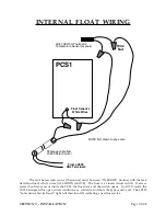
3. The attic temperature sensor is connected in series with the white internal
float leads located on the right side of the PCS1 by the electrical clamp. The internal
float is a normally closed switch which opens if the water in the base pan rises to
3/8Ó. This could only occur under a leak of the coil or a malfunction of the motor
and fan. Do not attempt to use this float for any other use. Contact ratings are only
15 ma and its intended use is strictly with the attic temperature sensor.
NOTE: If you raise this float by hand, the switch will open when the float is
off the base pan by approximately 1/8Ó. In actual water, 3/8Ó is required to raise the
float to an open circuit. The float will not reset until lowered all the way.
4. When the internal float rises and opens the circuit to the attic temperature
sensor, the LX220 interprets this as an extremely cold attic condition. It therefore
turns off the bypass valve and power to the PCS1.
CAUTION
:
This internal protection for the PCS1 is only available during the
time the LX220 is operating in ÒautomaticÓ. If the controller is placed into
O N
[manual override], it will ignore the attic temperature sensor and float.
5. A second [optional] relay can be installed in the LX220 to automate a pool
vacuum pump [i.e. Polaris, etc.]. This relay plugs into the
SWP
socket on the LX220.
6. On poor solar days, the pool's pump may not achieve a minimum amount
of desired filtration time. If a certain minimum filtration time is desired, a pump
timer should be installed as shown to bypass the LX220 during optimum solar time.
The pump timer should be set to start at 12 noon and run for the length of
minimum time desired.
Summary of Contents for PCS1
Page 7: ...SECTION 1 SYSTEM ARRIVAL Page S1 1 SECTION ONE SYSTEM ARRIVAL...
Page 22: ...SECTION 2 HEATING DATA Page S2 1 SECTION TWO HEATING DATA...
Page 28: ...BTUS Vs GPM BTUS Vs T SECTION 2 HEATING DATA Page S2 7...
Page 34: ...SECTION 3 INSTALLATION Page S3 1 SECTION THREE INSTALLATION...
Page 65: ...Attic Installation Photos SECTION 3 INSTALLATION Page S3 31...
Page 66: ...Attic Installation Photos SECTION 3 INSTALLATION Page S3 32...
Page 88: ...SECTION 4 SERVICE Page S4 1 SECTION FOUR SERVICE...
Page 99: ...Common Questions Page 1 of 10 COMMON QUESTIONS...
Page 109: ...Dictionary of Terms Page 1 of 4 DICTIONARY OF TERMS...


