Sentry 5000-32-IT Controller
Page 47 of 82
Processing Mode Asterisks
Screen Colors
Banner Color
Representation
Red blinking
At least one of the sensor modules has an Alarm that has not been
acknowledged
Red solid
Alarms have been acknowledged and at least one of the sensor modules
continues to be in Alarm state
Amber
At least one of the sensor modules is in Warning state
Blue
At least one of the sensor modules is in trouble state
Green
All sensors normal, no trouble, no alarms
Sensor Bar Color
Representation
Red blinking
The sensor module has an Alarm that has not been acknowledged
Red solid
Alarms have been acknowledged and the sensor modules continues to be in
Alarm state
Amber
The sensor module is in Warning state
Gray
The sensor module is in Trouble state
Green
The sensor module is normal, no trouble, no alarms
8.3
Navigation
This section discusses the areas of the display that can be touched to make a selection. Navigation areas
highlight when selected.
The following navigation rules apply to all screens unless otherwise indicated.
•
All menu page navigation begins by touching the Mode key
•
Sub-menu navigation may be scrolled by either touching the Mode key repeatedly
or by pressing the Up and Down keys
•
The primary menu screens include:
o
Alarm Management
o
Calibration Management
o
Access Management
o
History Management
o
System Management
o
Module Summary
•
To access the menu screens
– click the desired
menu in the Detail Bar (
Section
) then touch the
Enter (E) key
•
To access a device/sensor
– select the desired
device/sensor in the Information Area (
Section
) and touch the E key
o
Press the Down key to view additional information
WARNING: Do not use metal objects to touch the surface of the Touch Panel screen as these
objects may damage the screen surface. A fingertip, a plastic stylus or a pencil eraser
work well to input data on the Touch Panel and will not damage the surface.
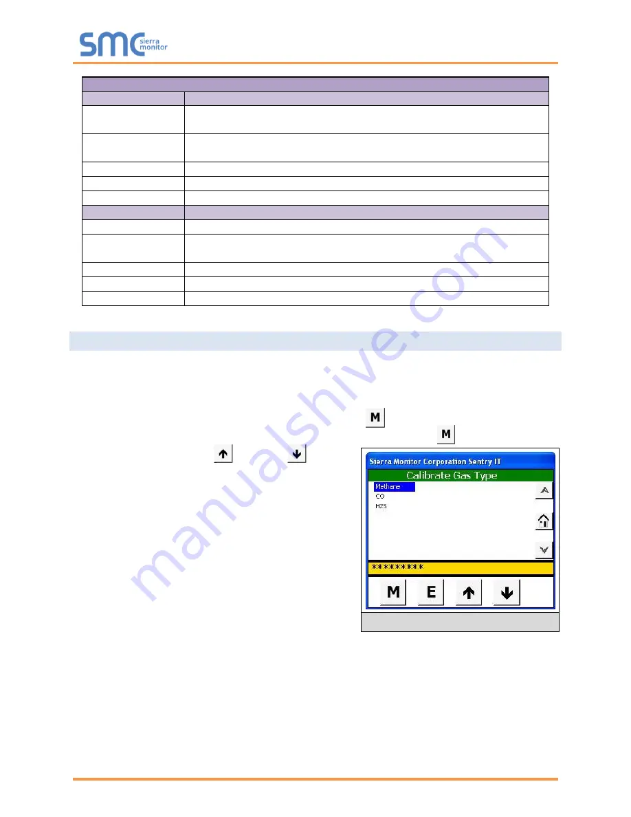
The touch panel indicates that the system is processing information by displaying a series of asterisks
(*****) in the detail bar. When the system is processing information user input is ignored. (see
Calibrate
Gas Type
screen)
Summary of Contents for Sentry 5000-32-IT
Page 28: ...Sentry 5000 32 IT Controller Page 28 of 82 Figure 15 Analog Input Wiring ...
Page 29: ...Sentry 5000 32 IT Controller Page 29 of 82 Figure 16 PSG Sentry Classic Wiring ...
Page 30: ...Sentry 5000 32 IT Controller Page 30 of 82 Figure 17 Modbus Wiring ...
Page 31: ...Sentry 5000 32 IT Controller Page 31 of 82 Figure 18 Top Board Relay Digital Output Wiring ...
Page 32: ...Sentry 5000 32 IT Controller Page 32 of 82 Figure 19 Analog Output Wiring ...
Page 33: ...Sentry 5000 32 IT Controller Page 33 of 82 Figure 20 Digital Input Wiring ...
Page 34: ...Sentry 5000 32 IT Controller Page 34 of 82 Figure 21 Bottom Board Relay Wiring ...


