Sentry 5000-32-IT Controller
Page 69 of 82
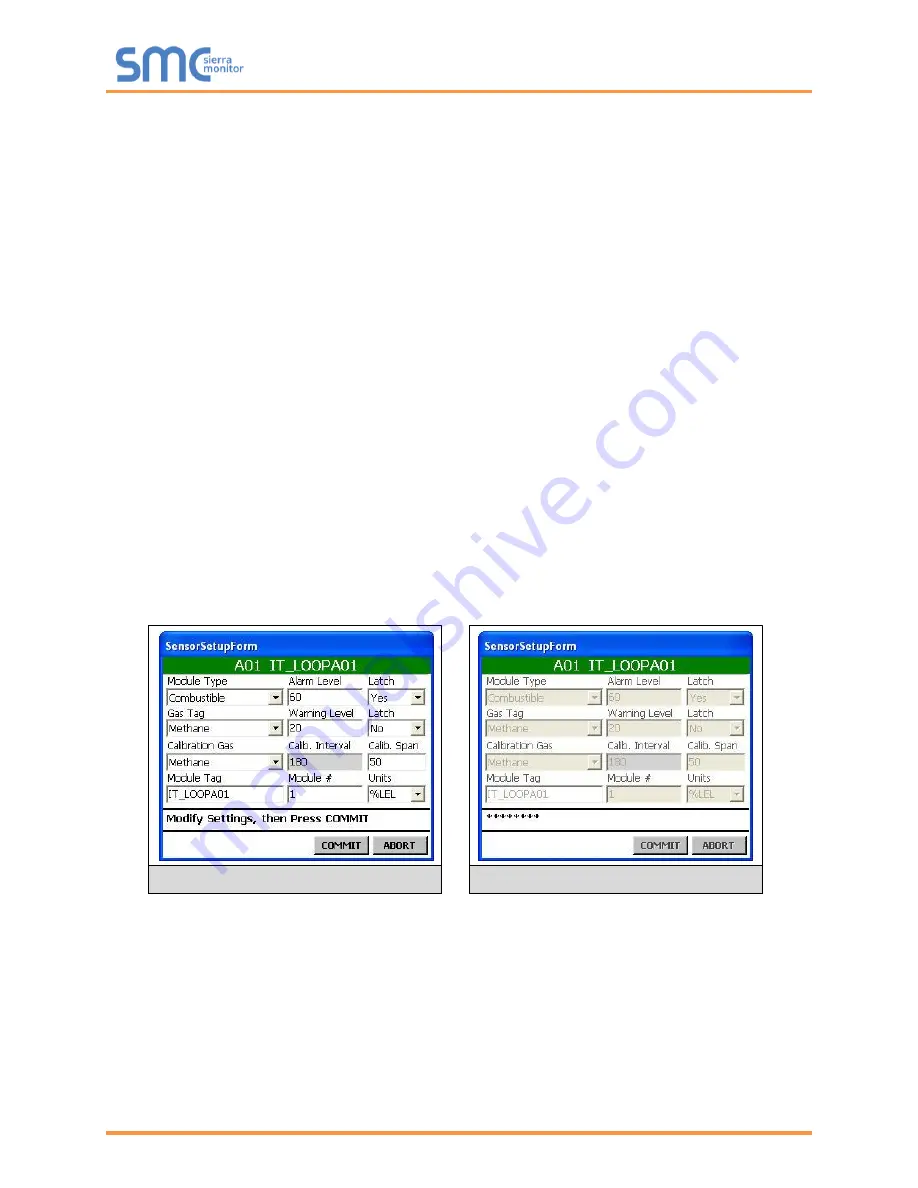
To define the sensor module attributes:
NOTE: Fields with gray area are not selectable or programmable.
•
Select Module type from drop down menu
•
Touch the Alarm Level field to display the Keyboard
o
Type the alarm level and touch the keyboard return key
•
Select the Latch on Alarm field (Y or N) from drop down menu
•
Select Gas Type from drop down menu
•
Touch the Warning Level field to redisplay the keyboard
o
Type the warning level and touch the keyboard return key
•
Touch the Latch on Warning field (Y or N) from drop down menu
•
Select Calibration Gas field from drop down menu
•
Touch the Calibration Span field to display the Keyboard
o
Type the calibration span and touch the keyboard return key
•
Touch the Module Tag field to display the Keyboard
o
Type the Module name and touch the keyboard return key
•
Touch the Module # field to display the Keyboard
o
Type the module number and touch the keyboard return key
•
Select Unites from drop down menu
•
Touch Commit to save the parameter information
o
System will display sequence of “***” characters to indicate save function.
•
Touch Enter (E) when finished
Modify Settings
Commit to Save
Summary of Contents for Sentry 5000-32-IT
Page 28: ...Sentry 5000 32 IT Controller Page 28 of 82 Figure 15 Analog Input Wiring ...
Page 29: ...Sentry 5000 32 IT Controller Page 29 of 82 Figure 16 PSG Sentry Classic Wiring ...
Page 30: ...Sentry 5000 32 IT Controller Page 30 of 82 Figure 17 Modbus Wiring ...
Page 31: ...Sentry 5000 32 IT Controller Page 31 of 82 Figure 18 Top Board Relay Digital Output Wiring ...
Page 32: ...Sentry 5000 32 IT Controller Page 32 of 82 Figure 19 Analog Output Wiring ...
Page 33: ...Sentry 5000 32 IT Controller Page 33 of 82 Figure 20 Digital Input Wiring ...
Page 34: ...Sentry 5000 32 IT Controller Page 34 of 82 Figure 21 Bottom Board Relay Wiring ...


