


- 12 -
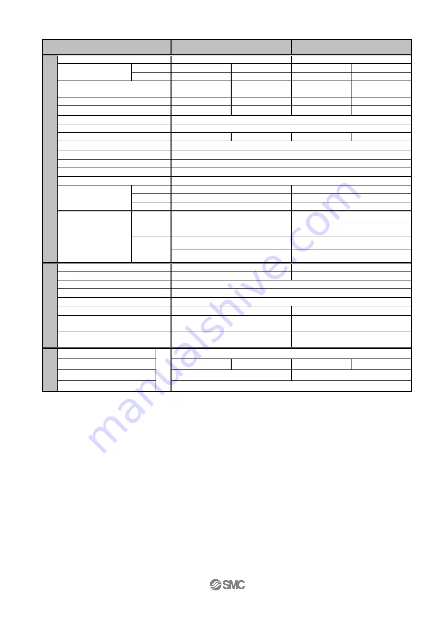
Servo Motor(24VDC) /D Type
2
1
5
2.5
0.5
0.25
2
1
7.5 to 11
5 to 7.5
17.5 to 35
10 to 20
10 to 200
20 to 400
10 to 200
20 to 400
10 to 20
20
10 to 20
20
4
8
5
10
Type
24
2.5
300
48
Loc
k uni
t s
pec
ifi
ca
tio
n
N
ot
e6)
No excitation operating type
24+/-10%
4
Rated voltage [VDC]
Power consumption [W]
Note7)
3.6
Holding force [N]
20
28
84
124
58
84
Horizontal : 4
Vertical : 7
Incremental A/B phase (800 pulse/rotation) / Z phase
Horizontal : 2
Vertical : 15
24+/-10%
10
30
Servo motor (Servo 24VDC)
Moment max. power
consumption [W]
Note5)
Power consumption [W]
Note3)
Standby power consumption
when operating [W]
Note4)
Encoder
Rated voltage [VDC]
E
lec
tr
ic
s
p
ec
ifi
cat
ion
Motor size [mm]
Motor type
Motor output [W]
Linear guide (circulating type)
Weight
[kg]
Without lock
75st : 0.70
100st : 1.70
50st : 0.57
50st : 1.25
With lock
50st : 0.66
Vertical
LESH16DA
50 , 100
Pushing speed [mm/s]
Note1)
Size
LESH8DA
Speed [mm/s]
Pushing force [N] 50to100%
(LESH8[ ]A:50 to 75%)
Note1)
Work load
[kg]
Horizontal
Operating temp. range [
℃
]
5 to 40
Positioning repeatability [mm]
+/-0.05
Screw lead [mm]
Impact / vibration resistance
[m/sec
2
]
Note2)
50 / 20
Actuation type
Slide screw
Guide type
Acceleration/Deceleration [mm/s
2
]
5,000 or less
Ac
tu
at
or
s
p
ec
ifi
cat
ion
Stroke [mm]
50 , 75
Operating humidity range [%RH]
90 or less (No condensation)
50st : 1.36
75st : 0.79
100st : 1.81
Static Allowable
Moment
[Nm]
Pitching
11
50st:26 / 100st:43
Yawing
11
50st:26 / 100st:43
Rolling
12
49
Note 1) The accuracy of the pushing force is ±20% of the max. pushing force.
The setting for the pushing force is 50-75% of LESH8[]A pushing force.
Note 2) Impact resistance: No malfunction occurred when the actuator was tested with a drop tester in both an
axial direction and a perpendicular direction to the lead screw.
(The test was performed with the actuator in the initial state)
Vibration resistance: No malfunction occurred in a test ranging between 45 to 2000 Hz. Test was
performed in both an axial direction and a perpendicular direction to the lead screw.
(The test was performed with the slide table in the initial state.)
Note 3) The "Power consumption" (including the controller) is for when the actuator is operating.
Note 4) The "Standby power consumption when operating" (including the controller) is for when the actuator is
stopped in the set position with no applied force in the direction of the actuator movement.
Note 5) The "Momentary max. power consumption" (including the controller) is for when the actuator is operating.
This value can be used for the selection of the power supply.
Note 6) Only applies to actuators supplied with a lock.
Note 7) For the actuator with lock, please add the power consumption for the lock.