HGM8151 Genset Parallel Controller User Manual Page 64 of 66
17
ETHERNET INTERFACE
17.1
ETHERNET INTERFACE INTRODUCTION
ETHERNET port, used for controller monitoring, has two connection modes: network client mode and
web server mode.
NOTE:
After changing controller network parameters (e.g. IP address, sub network mask etc.) new settings will take
effect only after the controller is restarted.
17.2
NETWORK CLIENT MODE
When the controller is used as network client
,
it can be monitored via network port using TCP ModBus
protocol.
The procedure is the following:
1)
Set IP address and sub network of the controller. The IP address must in the same network
segment as the IP address of monitoring equipment (e.g. PC) e.g.: if monitoring equipment IP
address is 192.168.0.16, controller IP can be 192.168.0.18, sub network mask 255.255.255.0
2)
Connect the controller. It can be connected to the monitoring equipment directly using network
cable or via switchboard.
3)
The communication between the controller and monitoring equipment is carried out using TCP
ModBus protocol.
NOTE:
In this connection mode controller parameters can be set. SmartGen provides testing software for this
connection mode. Communication protocol can be obtained from the SmartGen service
17.3
CONTROLLER AND NETWORK CABLE CONNECTION
17.3.1
ILLUSTRATION
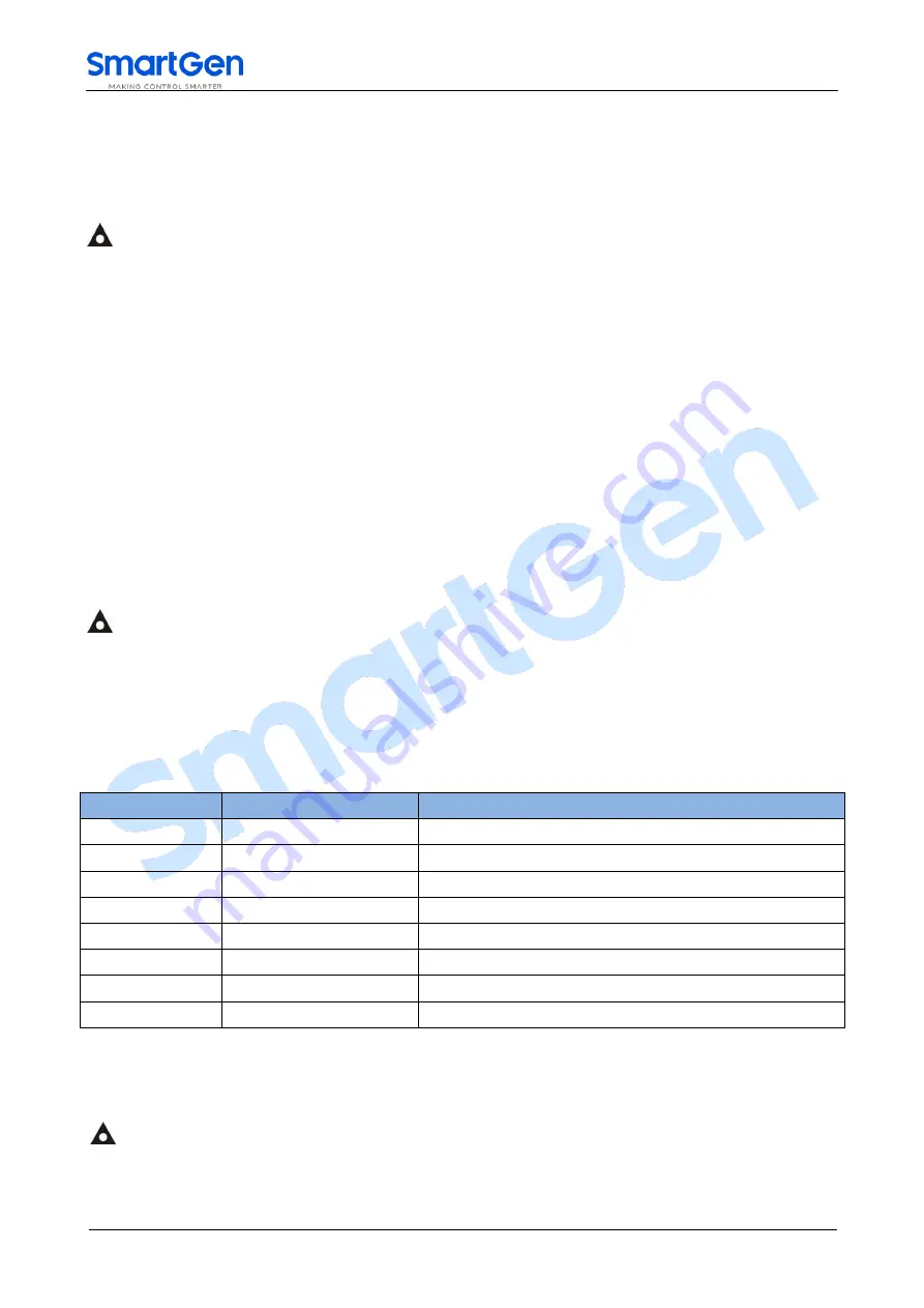
Table 48 Controller Internet Access
No.
Name
Description
1
TX+
Tranceive Data+
2
TX-
Tranceive Data-
3
RX+
Receive Data+
4
NC
Not connected
5
NC
Not connected
6
RX-
Receive Data-
7
NC
Not connected
8
NC
Not connected
17.3.2
CONTROLLER CONNECT WITH PC WITH A LINE OF CABLE
For this connection crossover cable must be used.
Crossover cable: EIA/TIA 568A standard on one end and EIA/TIA 568B on the other end.
NOTE:
If PC network port has Auto MDI/MDIX function, parallel cable can also be used.
17.3.3
CONTROLLER AND PC CONNECTION VIA SWITCHBOARD (OR ROUTER).
Parallel lines must be used.


