SMARTEYE
Netx Ethernet IP Control Unit User Manual
Page 41
Filename: netx IP Platform User Manual R0 .doc
…
In Control
A
M
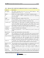
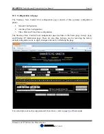
6. These two fields show the instance ID number for the PLC to Netx (on the left) and Netx
to PLC (on the right). Both these values are fixed and should not be changed. The PLC
interface logic must match these values.
7. This field represents the elapsed time in seconds since the last I/O message was received
from the PLC. This value should always be less than or equal to 1. If this value is greater
than 1 then communications between the Netx and PLC has faulted.
8. This field shows the last data packet sent from the Netx unit to the PLC.
9. This field shows the reader number for the label and error information that follows. In
this example, there are two readers shown because the Netx unit we are connected to is a
T-netx. There will be a single reader shown for the S-netx and eight readers shown for a
multi-netx.
10. This field shows the last label read by each of the readers in the Netx controller. If the
reader has not read a label since the last reboot then the last label read field will display a
zero.
11. This field shows the last error generated by each of the readers in the Netx controller. On
power-up, the Netx controller generates a power-up error for each reader. Therefore a
zero in this field means there have been no other errors since the last reboot other than
the initial power-up error.
12. The ‘Refresh Page’ button updates the page with the most current data.
11.0 Power-Up
After the Smarteye Netx Control Unit has been mounted and the DC power is terminated, an
initial checkout can be completed.
When power is applied, the Smarteye Netx Control Unit reads the setup configuration and
initializes its internal data. It then waits for a connection from the PLC on port 44818. After a
connection has been established the Netx Control Unit will begin sending data to the PLC.
The Smarteye Netx Control Unit always creates an 'error 0' message for each reader at power-up.
12.0 Communication
The Smarteye Netx Control Unit has two communication channels: the Ethernet IP control port
and the auxiliary port. The Ethernet control port accepts connections from a programmable
controller and provides the host system with label information from the Smarteye readers. The
auxiliary port connects to a user display terminal or laptop computer and is used for
troubleshooting. With the Smarteye Bluetooth option, the auxiliary port can be set up to function
as a Bluetooth interface. In this mode, a Bluetooth enabled device in conjunction with
Smarteye’s Bluetooth interface software, can be used to acquire real-time reader activity and
historical data wirelessly.
Summary of Contents for Multi-netx
Page 2: ......
Page 51: ......
Page 52: ......
Page 53: ......
Page 54: ......
Page 55: ......
Page 56: ......
Page 57: ......
Page 59: ......
Page 60: ......
Page 61: ......
Page 62: ......
Page 63: ......
Page 64: ......
Page 65: ......
Page 67: ......
Page 68: ......
Page 69: ......
Page 70: ......
Page 71: ......
Page 72: ......
Page 73: ......
Page 74: ......
Page 75: ......
Page 76: ...www smarteyecorporation com ...


