


Sunny Island
Installation & Operating Instructions
BWRI33-12:EE
- 47 -
SMA Regelsysteme GmbH
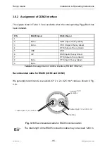
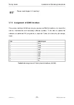
3
2
1
4
8
5
G
3
3
2
1
4
8
5
G
3
3
2
1
4
8
5
G
3
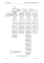
MOSR15-SP
MOSR15-SP
MOSR15-SP
Resistors
under the Piggy-
Back module must
be removed
Resistors
under the Piggy-
Back module must
be removed
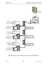
2 Sunny Boy
nd
Last Sunny Boy
(max. 50)
1 Sunny Boy
rst
Connect shield
to case (PE)
Termination for
last Sunny Boy:
Jumper 1
mounted
Sunny Island
(COM 2)
Resistors
under the Piggy-
Back module must
be removed
Termination:
Jumpers
mounted
not
Termination:
Jumpers
mounted
not
6
9
3
8
5
Plug-in DB9
680
Ω
7
680
Ω
Connect shield
to case (PE)
Connect shield
to case (PE)
680
Ω
6
8
0
Ω
1
2
0
Ω
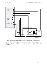
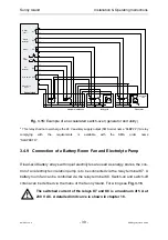
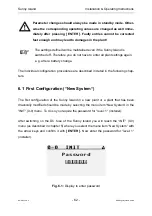
Fig. 3.20: Connection of Sunny Boys at Sunny Island’s COM2 (RS485)


