


Sunny Island
Installation & Operating Instructions
BWRI33-12:EE
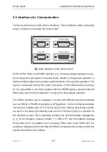
- 40 -
SMA Regelsysteme GmbH
Sunny Island
13
14
13
14
N
L
F2
M
M
L
N
external Distribution
2 A
K7
K8
Battery
fan
Battery
circulation
AC-
Outlet
Electrolyte
Pump
Battery Room
Fan
SI-
BPRE
SI-
BPRE
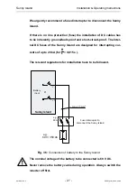
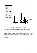
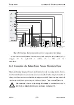
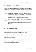
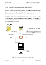
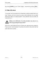
Fig. 3.16: Connection of a battery room fan and electrolyte pump
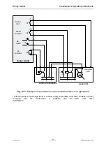
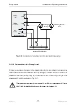
3.4.10 Connection of a Dump Load
If there is a surplus of energy in the island grid which is not utilized, but cannot be
stored either because the batteries are fully charged, it makes sense to connect an
additional consumer (dump load). It is connected to one of the relays not yet used
otherwise (K1 to K8) as shown in Fig. 3.17.
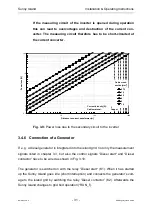
The switched current of the relays K1 to K8 is a maximum of 5 A at
230 V AC. A detailed limit curve is shown in chapter 18.


