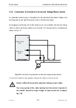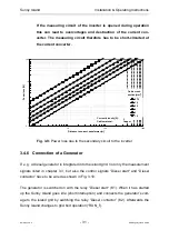
Sunny Island
Installation & Operating Instructions
BWRI33-12:EE
- 38 -
SMA Regelsysteme GmbH
Sunny Island
13
14
13
14
N
L
F2
G
L
N
external distribution
Generator
Diesel
start
Diesel
contactor
K1
K2
Generator
start
AC-
outlet
2 A
L
N
PE
L
N
2 A
L
N
Grid
L
N
utility grid
13
14
Mains
K3
13
14
L
N
Diesel sync.
input
Sync switch
SI-
BPRE
SI-
BPRE
SI-
BPRE
K5
24V=
SI-
BP24
*
+
-
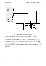
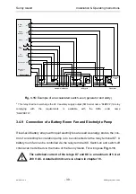
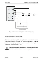
Fig. 3.14: Connection to generator and utility
*
This relay shall not overcharge the 24 V auxiliary supply output (SMA order name ”SI-BP24“)! A relay
complying with the requirements is available with the SMA order name
”SI-BPRETR“.
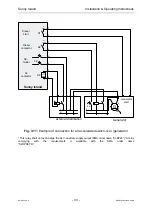
The switch-over times can also be reduced just by a little more expenditure (Fig.
3.15).

