Sunny Island
Installation & Operating Instructions
BWRI33-12:EE
- 147 -
SMA Regelsysteme GmbH
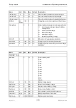
Name Unit
Min.
Max.
Default
Description
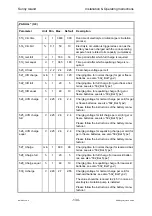
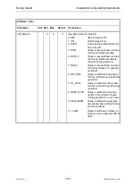
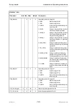
Pext L2
kW
-320
320
0
Generator active power at phase 2
Pext L3
kW
-320
320
0
Generator active power at phase 3
Iext Sum
A
0
640
0
Sum of generator current (three phases)
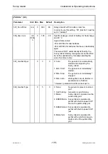
Psi L1
kW
-320
320
Grid active power of Sunny Island phase 1
Psi L2
kW
-320
320
Grid active power of Sunny Island phase 2
Psi L3
kW
-320
320
Grid active power of Sunny Island phase 3
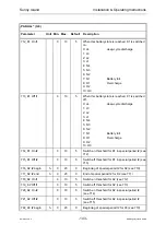
Bat State
L4
O3
L1
Current battery state
0= L4
1= L3
2= L2
3= L1
4= N4
5= N3
6= N2
7= N1
8= O1
9=O2
10=O3
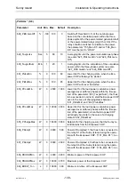
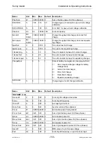
SOC act
%
-100
110
0
Battery state of charge
Pbat Sum
W
-32000 32000 0
Sum of battery power SI (three phases)
Ibat Sum
A
-320
320
0
Sum of battery current SI (three phases)
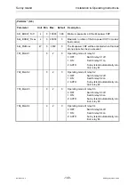
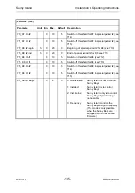
GenState
0
10
0 Generator
state
0=none not
active
1= off
OFF
2=glow glowing
up
3=crank cranking
4= warm
warming up
5=run
running
6=cool cooling
down
7=Stopp stopping
8=lock
locked after operation
9=fail
failure
10=fail_look locked after multiple failure
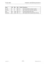
GenFail
0
6
0
Generator failure state
0=none
no failure
1=F_crank failure during cranking
2=F_warm failure during warming up
3=F_Run
failure in operation
4=F_Runlim gen. falls short of minimum power
5=F_Cool
failure during cooling down


