background image

Sirona Dental Systems GmbH

9 Operation 

Operating Instructions ORTHOPHOS XG

Plus 

DS/Ceph

9.7 Selecting the exposure parameters 

59 87 594 D 3352
D 3352.201.01.18.02

67

9.7

Selecting the exposure parameters

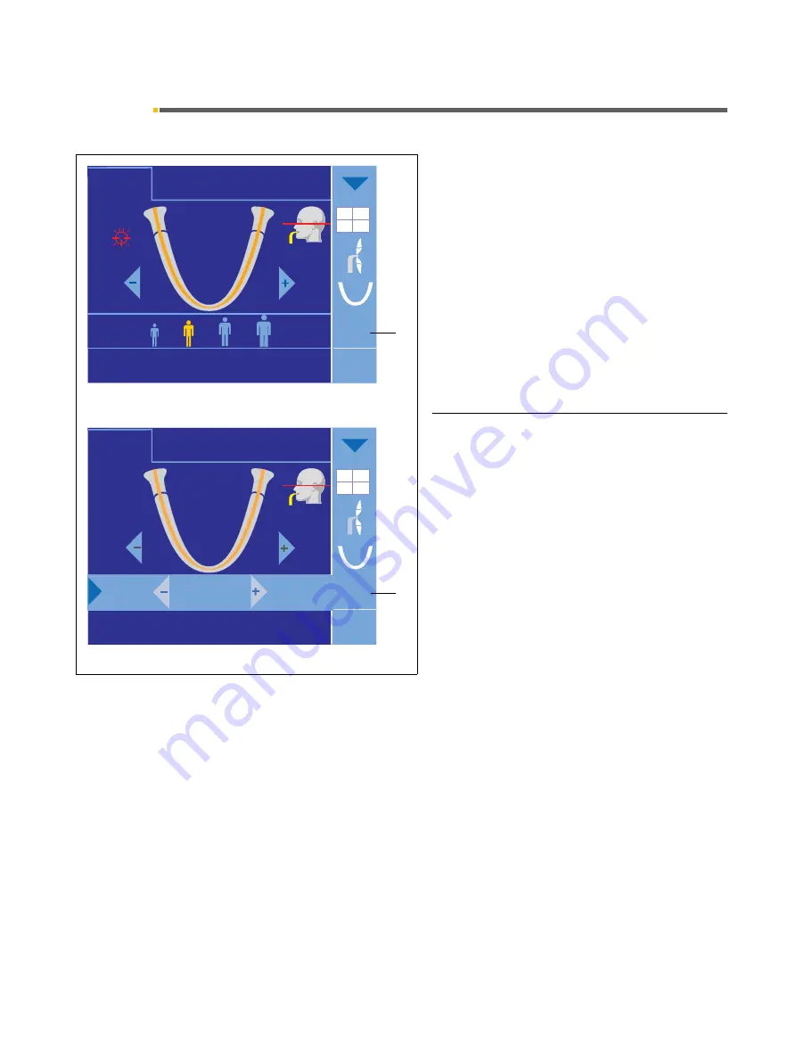
The patient symbol keys are factory-programmed with 
kV/mA combinations:

Select the exposure parameters by touching one of 
the four patient symbols.
The selected patient symbol is highlighted in orange 
and the corresponding kV/mA value is displayed in 
column (8) next to the patient symbols.

Modifying the exposure parameters manually

If the default kV/mA combinations do not provide satis-
factory results, you can preselect intermediate kV/mA 
values in the 

kV/mA

 submenu.

To open the submenu, touch the kV/mA display in col-
umn (8). The values can be adjusted with the –/+ keys. 
To close the submenu, touch the light blue arrow at the 
left margin of the submenu line. (See also section 

3.2 

“General touchscreen functions”

).

CEPH

PAN

PAN

1260

64kV

8mA

?

P1

AEC

TS

14,1s

10

62kV

8mA

Ready for exposure

SID = 19,6”

6 x 12”

SID = 19,6”

6 x 12”

CEPH

PAN

1260

10

64kV

8mA

?

P1

9,0 s

9,0 s

Quick

TS

Ready for exposure

Ready for exposure

8

8

Summary of Contents for Orthophos XG Plus DS/Ceph

Page 1: ...b loqelmelp udm apL l f...

Page 2: ...with the unit by reading through these Operating Instructions before taking any X rays of patients Please comply with the applica ble radiation protection regulations and warnings at all times These o...

Page 3: ...of 1 25 32 5 3 P10 normal view for children with significant dose reduction P10 A artifact reduced P10 C with a constant magnification factor of 1 25 33 5 4 P12 Slice thickness anterior tooth region...

Page 4: ...ing a cephalometric exposure 84 11 Transversal slices TSA 87 11 1 Preparing a TSA exposure 87 11 2 Patient positioning 94 11 3 TSA universal bite block 98 11 4 Preselecting the exposure settings and r...

Page 5: ...if maintenance and repair are carried out only by ourselves or agencies expressly authorized by us and if components affecting safe oper ation of the system are replaced with original spare parts upon...

Page 6: ...n IEC 60601 1 2 This system may be operated in a residential area Portable and mobile RF communications equipment may interfere with medical electrical equipment There fore the use of mobile wireless...

Page 7: ...ceptional cases a third person may provide assistance but not the practice staff During the whole exposure visual contact with the patient and the unit must be maintained In case of malfunctions cance...

Page 8: ...sics of electrostatic discharges which can occur in the practice and the destruction of elec tronic components which may result if such components are touched by electrostatically charged USERS The co...

Page 9: ...func tions in dental X ray CEREC systems The circuits must be miniaturized to a very high degree in order to include as many functions as possible on these chips This leads to structure thicknesses a...

Page 10: ...onsumption 2 kVA Power output of tube assembly 90 kV 12 mA 1080 W with any radiation time Tube voltage 60 90kV for 90 kV max 12 mA Tube current 3 16mA at 16 mA max 66 kV Maximum setting range 60 kV 3...

Page 11: ...protection against ingress of water Year of manufacture on the rating plate Operating mode Continuous operation Long term power output 100W Anode material Tungsten Exposure parameters for determining...

Page 12: ...4 GB database 50 MB SIDEXIS installation RAM min 256 MB Drives CD ROM MOD drive min 640 MB one per system network Operating system Minimum requirement Windows 2000 Workstation SP 4 Windows XP Professi...

Page 13: ...Heating curve of tube housing Central X ray beam anode angle 0 60 120 180 240 300 360 420 480 540 600 660 720 10 20 30 40 50 60 70 80 90 100 110 120 130 HUx104 t min 1 HU 1 35 Joule 0 1 2 3 4 5 6 5 10...

Page 14: ...lectable upper jaw lower jaw and single quadrants P1A C P2 A C P10 A C Selectable upper jaw lower jaw image detail P12 Temporomandibular joint views TM2 1 TM2 2 with angle input TM2A 1 TM2A 2 with ang...

Page 15: ...ort 7 Temple supports 8 Pushbutton for sensor image receptor removal 9 Sensor image receptor according to the unit ver sion for XG Pan for XG Ceph for XG Pan TSA for XG Ceph TSA 10 Exposure release bu...

Page 16: ...izer 23 Scale for vertical nose support adjustment 24 Projection scale 25 Ear plugs with holders 26 Carpus support plate Magnification of the lateral view With this exposure technique a metal scale 24...

Page 17: ...e upper right corner for panoramic and TSA images will guide you in positioning the patient s head A The gray patient s head icon shows the head pos ture straight FH bent forward with open or closed m...

Page 18: ...ith constant magnification P1A artifact reduced display 7 Display of head posture FH or bent forward or back ward mouth open or closed with reference line for the chosen program 8 Submenu column optio...

Page 19: ...s P1 P2 and P10 including constant magnification and artifact reduced display The preselected type of exposure is also displayed in the submenu column 8 Selection of individual quadrants The full vers...

Page 20: ...isplays and indicate how the half views and the individual quad rants are associated with the patient Individual quadrant exposures are possible only in the XG Plus full version The program duration f...

Page 21: ...d display For preselection touch the corresponding tooth symbol in the submenu line 4 Manual setting of kV mA values If the default kV mA combinations do not provide satis factory results you can pres...

Page 22: ...corner of the touchscreen the arrow will point upward then After having made your selections you can return to pro gram level 1 only by touching the blue arrow 9 once again NOTE i When you confirm the...

Page 23: ...ht arrow will become a double arrow then You can close this menu again only by touching the blue double arrow 9 in the upper right corner The display always returns to the standard menu program level...

Page 24: ...EPH exposures you can only change the patient icon preference 2nd icon from the left as per factory setting For TS exposures you can change the slice thickness preference left icon for the thinnest sl...

Page 25: ...upper fly out menu you can switch off the clicking tone of the touchscreen by activating the crossed out musical note symbol In the lower fly out menu you can adjust the intensity of the touchscreen...

Page 26: ...long to be displayed all at once a scroll bar for paging up or down appears on the right You can activate the touchscreen click tone and touchscreen intensity setting fly out menus from the help scre...

Page 27: ...left for tem poromandibular joint viewsOrder No 59 80 607 E Ear holders for temporomandibular joint supports 10 pieces Order No 18 88 838 E1 Contact pads for temporomandibular joint supports 10 pcs O...

Page 28: ...cent drawing All of the following drawings and descriptions contained in these operating instructions show this arrangement In ORTHOPHOS XG units delivered until October 2006 the holders of the temple...

Page 29: ...nd temple supports 500 pcs Order No 59 68 263 Dimensions 150 mm x 47 mm S For bite block 500 pcs Order No 33 14 072 Dimensions 43 mm x 21 mm T For chin rest and bar 100 pcs Order No 59 32 603 Dimensio...

Page 30: ...een for maxillary TSA images where thealveolar ridge of the patient s head is aligned parallel to the floor to position the patient a little lower in relation to the beam path 5 pcs Order No 60 32 937...

Page 31: ...iew or an individual quadrant view in the full version see section 3 2 General touchscreen functions P1 Normal view Yellow bite block or contact segment or chin rest with bite block rod and bite block...

Page 32: ...r a maxil lary or mandibular view or an individual quadrant view in the full version see section 3 2 General touchscreen functions P2 normal view limited to teeth without ascending rami Yellow bite bl...

Page 33: ...drant view in the full version see section 3 2 General touchscreen functions P 10 normal view status preferably for children Yellow bite block or contact segment or chin rest with bite block rod and b...

Page 34: ...unt forward or to count backward depending on the starting position for program sequence see section 3 2 In addition you can preselect in the half view selection submenu at the top of column 8 whether...

Page 35: ...select in the half view selection submenu at the top of column 8 whether you want to generate a half view of the right or left side see also section 3 2 General touchscreen functions no selec tion of...

Page 36: ...rward or to count backward depending on the starting position for program sequence see section 3 2 Yellow bite block or contact segment or chin rest with bite block rod and bite block or bar Head incl...

Page 37: ...head icon in dicates the reflection line of the light localizer Activate TM1 1 On completion of TM1 1 the message Please wait appears in the comment line and the unit automati cally returns to its sta...

Page 38: ...returns to its starting position Angle preselection for temporomandibular joint programs TM1 1 TM1 2 and TM1A 1 TM1A 2 These programs allow for angle preselection 0 5 10 and 15 for the temporomandibul...

Page 39: ...ayed on the touchscreen head icon is used here for orientation only Activate TM2 1 On completion of TM2 1 the message Please wait appears in the comment line and the unit automati cally returns to its...

Page 40: ...e R button again the unit returns to its starting position Angle preselection for temporomandibular joint programs TM2 1 TM2 2 and TM2A 1 TM2A 2 These programs allow for angle preselection 0 5 10 and...

Page 41: ...ral ascending rami TM3 Temporomandibular joints lateral ascending rami Insert temporomandibular joint supports 1 and 2 Head inclination using the FH The line displayed on the touchscreen head icon in...

Page 42: ...ction TM4 Temporomandibular joints in posterior anterior projection Insert temporomandibular joint supports 1 and 2 To largely prevent overlaps head inclination to wards anterior in relation to the FH...

Page 43: ...r joints lateral multislice 6 views in one image Insert temporomandibular joint supports 1 and 2 To largely prevent overlaps head inclination using the FH The line displayed on the touchscreen head ic...

Page 44: ...oromandibular joints multislice in posterior anterior projection 6 views in one image Insert temporomandibular joint supports 1 and 2 To largely prevent overlaps head inclination to wards anterior in...

Page 45: ...floor fractures Fit blue contact segment subnasally Fit temporomandibular joint supports 1 and 2 without ear holders but with contact pads Patient s head max reclined The line displayed on the touchs...

Page 46: ...mporomandibular joint supports 1 and 2 without ear holders but with contact pads Head inclination using the FH The line displayed on the touchscreen head icon in dicates the reflection line of the lig...

Page 47: ...orientation e g orbital floor fractures Fit blue contact segment subnasally Fit temporomandibular joint supports 1 and 2 without ear holders but with contact pads Patient s head max reclined The line...

Page 48: ...bite block or contact segment Fit temporomandibular joint supports 1 and 2 without ear holders but with contact pads Head inclination using the FH The line displayed on the touchscreen head icon in di...

Page 49: ...18 02 49 8 Program group multislice views 8 1 MS1 Multislice posterior tooth region MS1 Posterior tooth region multislice 6 views in one image Yellow bite block or contact segment Lower edge of mandi...

Page 50: ...iption Set main switch 1 to position I and wait approx 1 minute ATTENTION Due to the warm up phase of the screen backlight screen readability is poor for a few minutes after switch ing on the system T...

Page 51: ...lowing A Bite block height adjustment value in mm ranging from 810 to 1815 mm from the last patient set B The exposure program which was last used C The basic value 0 mm of the completely opened foreh...

Page 52: ...r s Manual As long as no connection with SIDEXIS is estab lished the message Switch SIDEXIS to ready for exposure state is displayed in the comment line of the Easypad touchscreen Once SIDEXIS is read...

Page 53: ...xposure template and get the SIDEXIS system ready for exposure When SIDEXIS is ready for the first exposure of the template the welcome screen with the selected pa tient s data from SIDEXIS appears on...

Page 54: ...oups Exposure with chin rest and bite block The patient places himself or herself in front of the control mirror Using the up or down arrow key adjust the height of the unit so that the chin of the pa...

Page 55: ...ed Stretched cervical vertebrae prevent diminished density in the anterior tooth region In special cases you may also position a seated patient using e g a dentist stool RIGHT WRONG T R CEPH PAN TS LS...

Page 56: ...clination for the FH setting Briefly touch the up 30 or down 31 arrow key for height adjustment Align the center of the anterior teeth or of the face with the central light line C Press key 29 on the...

Page 57: ...n line This is easier if you place a cotton pellet between them Proceed as for an exposure with chin rest and bite block Difference The patient places his or her chin on the chin rest For optimal posi...

Page 58: ...tion of the bite block Upper anterior teeth into the indentation lower ante rior teeth pushed forward as far as possible with contact segment For patients without anterior teeth Adjust the height of t...

Page 59: ...on for the FH setting Briefly touch the up 30 or down 31 arrow key on the Easypad for height adjustment Align the center of the anterior teeth or of the face with the central light line C Press key 29...

Page 60: ...n place The symbol display will change as soon as the metallic blade A dips into the coil body Check every day whether the arrows and the head sym bol are displayed consistently If that is not the cas...

Page 61: ...ght adjustment motor starts slowly and then in creases its speed Press and hold down the height adjustment key until the unit has reached the desired height The patient seizes the handles Have the pat...

Page 62: ...play also changes accordingly Travel stops immediately when the nominal position has been reached a double beep sounds and the green arrows previously displayed disappear An sign appears next to the d...

Page 63: ...de mandrel of the lever 1 on the bite block plate and the eyelet of the con necting rod 2 slightly in the directions of the arrows and unhinge the lever 3 Swing the bite block 3 upward into a vertical...

Page 64: ...the orientation right left of the temporo mandibular joint supports specified on page 28 Using the up or down arrow keys on the Easy pad adjust the height of the unit so that the ear hold ers are at...

Page 65: ...E i For devices until October 2006 Please observe the orientation right left of the temporo mandibular joint supports specified on page 28 9 4 Finishing the preparations panoramic views If the light l...

Page 66: ...ymbol in the center area Programming is done by touching the memory symbol 1 9 6 Changing the startup settings in program level 4 You can access program level 3 by touching the disk icon 21 in level 4...

Page 67: ...column 8 next to the patient symbols Modifying the exposure parameters manually If the default kV mA combinations do not provide satis factory results you can preselect intermediate kV mA values in t...

Page 68: ...ematurely Note that radiation may be released several times during an exposure cycle Wait until the unit has completed the exposure cycle The exposure cycle is complete when the touchscreen comment li...

Page 69: ...on the exposure program are again displayed on the touchscreen Acknowledge the exposure time actually needed by pressing the return key R Then reset the rotating element to its starting posi tion by...

Page 70: ...ion of the tube Premature release of a new exposure is prevented by the automatic exposure blocking function When you press the exposure release button the mes sage Ready for exposure in XX seconds ap...

Page 71: ...he radiation indicator 32 lights up for approx one sec ond for a function test The four display fields on the display panel B light up and program P1 appears with the corresponding values after a shor...

Page 72: ...2 a p symmetric S or C4 for car pus views R button move into Ceph starting position appears in the comment line ATTENTION Make sure that no patient is in the movement range of the PAN rotating element...

Page 73: ...off at the back If program C3 has been preselected you can activate subprogram C3 F by touching C3 on the touch screen NOTE i By default the patient s face points to the right in the dis play of later...

Page 74: ...and push it up to the stop it is not necessary to press the pushbutton 8 when doing this If the sensor 9 is not fully inserted into the slot on the cephalometer the help message Plug sensor into Ceph...

Page 75: ...s and jewelry in the head and neck area as well as all removable dental prostheses Adjusting the height of the unit Move the cephalometer to approximately the height of the patient s head and have the...

Page 76: ...ocalizer is on a red light localizer symbol is displayed on the touchscreen NOTE i Make sure that the light beam does not hit the patient s eyes laser light The light localizer switches off automatica...

Page 77: ...views with shadowing in the upper cranial region C3 and C3 F exposures also support shadowing in the upper cranial region To do this touch the head icon in the Submenu column 8 and select the shadowi...

Page 78: ...d the sensor For a symmetrical p a view have the patient turn so that he she faces the sensor p a once height adjust ment is completed but before closing the ear plugs This applies to both the left ha...

Page 79: ...ograph off axial cra nial overview This exposure technique with the head reclined and the mouth open fully also supports shadowing in the thyroid area To do this touch the head icon in the Submenu col...

Page 80: ...s to both the left handed and the right handed ceph arm version Insert the ear plugs into the external auditory canals Hold the ear plug holders at their upper ends when doing this Select the kV mA va...

Page 81: ...carpus support plate 26 at its left and right side and push it into the two holes A until it engages To remove the carpus support plate seize it laterally and simply pull it out downward against a ce...

Page 82: ...satis factory results you can preselect intermediate kV mA values in this submenu 3 Shadowing in the upper cranial region only for programs C3 and C3 F C3 and C3 F lateral views let you choose if you...

Page 83: ...10 5 Making the basic settings in program level 3 To access the third program level touch the down arrow 20 in the second program level Programming the patient symbols You may enter new kV mA values...

Page 84: ...utton 10 While radiation is active the optical radiation indicator 32 is illuminated In addition an acoustic signal sounds throughout the entire radiation time ATTENTION Take care not to let go of the...

Page 85: ...t suitable for diagnostic purposes You must close the preview image again by touching the touchscreen The exposure mode exposure program tube voltage tube current real radiation time dose area product...

Page 86: ...exposure is prevented by the automatic exposure blocking function When you press the exposure release button the mes sage Ready for exposure in XX seconds appears in the comment line of the touchscree...

Page 87: ...posure Plug in TSA sensor Make sure that a TSA sensor is plugged into the PAN slot either PAN TSA or CEPH TSA ATTENTION DO NOT DROP THE SENSOR A shock sensor for detecting shocks or drops is built in...

Page 88: ...asuring the maxilla and up to the man dibular anterior teeth when measuring the mandible NOTE i The patient s overbite must be taken into account when placing the measuring caliper against his her man...

Page 89: ...ol at the top of the sub menu column The quadrant selection submenu appears Touch the quadrant where the tooth you want to ex amine is located The selected quadrant is highlighted in orange color The...

Page 90: ...light gray jaw half When you leave your finger on the corresponding ar row the depth indicator and the orange linear sensor automatically move into the related direction The following reference tables...

Page 91: ...pper jaw enter 0 mm For anterior teeth 21 upper jaw left or 31 lower jaw left enter 2 mm For anterior teeth 22 upper jaw left or 32 lower jaw left enter 4 mm For canine teeth 23 upper jaw left or 33 l...

Page 92: ...indicator jumps to 30 mm when you touch it in the rear segment the depth indicator jumps to 50 mm At the same time the submenu column 8 displays an icon for preselecting the slice thickness Slice thic...

Page 93: ...segment the depth indica tor jumps to 50 mm At the same time the submenu column 8 displays an icon for preselecting the slice thickness Slice thickness is preset to 2 mm You can also preselect slice...

Page 94: ...NOTE i We recommend that you perform a test cycle without ra diation with the T key prior to starting the exposure to make sure that the tube assembly and sensor do not col lide with the patient s hea...

Page 95: ...lization of the mandibular canal in the transversal slices can be achieved by aligning the canal parallel to the central X ray beam Since the central X ray beam is angled 7 degrees up from horizontal...

Page 96: ...er 2006 Please observe the orientation right left of the temporo mandibular joint supports specified on page 28 Maxillary molar teeth When you enter a depth of 15 mm or more the patient head symbol ch...

Page 97: ...patient a little lower in relation to the beam path The light localizer beam A which reflects also on the sensor can be used as an auxiliary tool Set the light beam to the upper edge of the TSA displ...

Page 98: ...p the lower part onto the pins of the upper part Bite block foam single use device 100 pcs Order No 61 41 449 Insert the universal bite block in the bite block holder and set the bite block slide acco...

Page 99: ...asurement with the TSA scale proves to be difficult or impossible you can use the average reference val ues listed in the following table for making the settings for premolar and molar exposures Pleas...

Page 100: ...pear NOTE i Following the exposure the TSA slice orientation with a longitudinal thick slice will be preselected as the default setting Changing the slice thickness only for the TSA slice orientation...

Page 101: ...s and molars in the upper or lower jaw and for each of the 4 patient symbols Subse quently you can save these values by touching the pro gramming key 1 The programming of patient symbols can be perfor...

Page 102: ...alternative During a TSA exposure three slice views are taken Slices for anterior and canine teeth are 1 mm deep slices for the molar region are approx 2 mm deep You can preset the slices for the mol...

Page 103: ...ative 59 87 594 D 3352 D 3352 201 01 18 02 103 Example implant To make clear which one of the three TSA views shows which portion of the dental arch steel balls were fitted prior to image acquisition...

Page 104: ...slice default Can be used with millimeter precision Angle preselection possible Please note that the magnifications of the partial images vary according to the technique concerned TS slices alternati...

Page 105: ...uni versal bite block in this setting black mark setting NOTE i The partial image sequence is dependent on the select ed half side R L Make sure that the anterior tooth region 0 mm can be displayed i...

Page 106: ...GPlus DS Ceph 59 87 594 D 3352 106 D 3352 201 01 18 02 Combined TS cross slices with a longitudinal thick slice alternative Can be used for TS slices with thick longitudinal slice with millimeter prec...

Page 107: ...4 s 7 4s 4 3s 62 8 64 8 68 8 73 8 P2A 18 0s 12 1s 11 6s 6 7s 15 0s 11 8s 7 4s 4 3s 62 8 64 8 68 8 73 8 P2C 16 8s 11 7s 11 6s 6 7s 13 7s 9 7s 8 6s 5 0s 62 8 64 8 68 8 73 8 P10 16 4 s 11 6s 11 6s 6 7s 1...

Page 108: ...69 15 73 15 P2A 18 0s 12 1s 11 6s 6 7s 15 0s 11 8s 7 4s 4 3s 62 8 64 8 69 15 73 15 P2C 16 8s 11 7s 11 6s 6 7s 13 7s 9 7s 8 6s 5 0s 62 8 64 8 69 15 73 15 P10 16 4 s 11 6s 11 6s 6 7s 11 4 s 9 4 s 7 4s 4...

Page 109: ...3s 62 16 64 16 69 15 73 15 P2A 18 0s 12 1s 11 6s 6 7s 15 0s 11 8s 7 4s 4 3s 62 16 64 16 69 15 73 15 P2C 16 8s 11 7s 11 6s 6 7s 13 7s 9 7s 8 6s 5 0s 62 16 64 16 69 15 73 15 P10 16 4 s 11 6s 11 6s 6 7s...

Page 110: ...60 60 60 60 60 62 64 66 69 71 73 77 80 84 90 mA 9 10 12 14 16 16 16 16 15 15 15 14 14 13 12 Table Cephalometric exposures Program Max radiation time Quickshot Max exposure time Factory programmed val...

Page 111: ...10 s A 60 8 62 8 64 8 64 8 Mandibular canines 6 14 mm 10 s A 60 8 62 8 64 8 64 8 Maxillary canines 6 14 mm 10 s B 61 9 62 10 64 10 64 10 Mandibular premolars 15 35 mm 12 3s C 68 12 71 12 73 12 77 11...

Page 112: ...1 Maxillary premolars 15 35 mm 8 2 s C 68 12 71 12 73 12 77 11 Mandibular molars 36 65 mm 8 2 s C 68 12 71 12 73 12 77 11 Maxillary molars 36 65 mm 8 2 s C 68 12 71 12 73 12 77 11 Table 5 longitudinal...

Page 113: ...es 6 14 mm 10 0s B 61 9 62 10 64 10 64 10 Mandibular premolars 15 35 mm 12 3s C 68 12 71 12 73 12 77 11 Maxillary premolars 15 35 mm 12 3s C 68 12 71 12 73 12 77 11 Mandibular molars 36 65 mm 13 0s C...

Page 114: ...H3 01 R button move into starting position The rotating element is not in the starting position H3 20 R button confirm exposure data The exposure data have not been acknowledged yet H3 21 Close the do...

Page 115: ...tion 2 Errors caused by system overload Acknowledge the error message Repeat the procedure step after a certain waiting time If the error message reappears prolong the waiting time If the error state...

Page 116: ...system operation If the error occurs repeatedly switch the system off and back on if the error reoccurs contact your Customer Service This error group includes all errors which may occur spontaneously...

Page 117: ...from the Internet at www sirona de SER VICE Downloads Care cleaning agents If you do not have Internet access you can use one of the following two ways to order the list Order from your local dental d...

Page 118: ...addition to the annual check to be carried out by the system owner or authorized persons preventive main tenance must be performed after 4 7 and 10 years and then at two year intervals 15 3 Image qua...

Page 119: ...ing of equipment permanently please proceed as follows In Germany To initiate return of the electrical device please send a disposal request to enretec GmbH You can find a form for placing a disposal...

Page 120: ...ogram level touch the down ward pointing arrow 20 This brings you to the third program level basic set tings In the third program level touch the keypad sym bol A A field with a keypad symbol and a ke...

Page 121: ...y alternately Failed and the incorrect activa tion key code If you have entered a correct code the message Accepted appears telling you that the extended functions have been successfully activated Che...

Page 122: ...XX XXX XX XXX You can read the IP address e g by calling up the info screen on the touchscreen of the ORTHOPHOS XG Each time the ORTHOPHOS XG web pages are called up the adjacent dialog box will be di...

Page 123: ...PHOS XG system To do this click ActivationCode A website with an input field for the activation key code is then displayed Enter this key code in the ActivationCode field Confirm your entry by clickin...

Page 124: ...you are calling up the ORTHOPHOS XG web page for the first time the following procedure is required The adjacent safety security certificate will be displayed if the certificate of the ORTHOPHOS XG ha...

Page 125: ...t Wizard Certificate Store dia log box then appears Click Next The Certificate Import Wizard Complete the wizard dialog box then appears Click Finish When the following security warning appears please...

Page 126: ...17 Activating functions Sirona Dental Systems GmbH 17 2 Via web browser on the PC Operating Instructions ORTHOPHOS XGPlus DS Ceph 59 87 594 D 3352 126 D 3352 201 01 18 02...

Page 127: ......

Page 128: ...t K p a p d e OMMQJOMNM p W m d a PPROKOMNKMNKNUKMO MQKOMNM KJk KW NNO RST f p a p d e c PN SQSOR _ d K K l k K RV UT RVQ a PPRO...

Reviews: