


Shenzhen Santone SilverCon
Email: [email protected]
Web: www.silver-con.com
Page: 7
SCW001 User Manual
Chapter 3: Hardware Description and Hardware Installation
3.1 Front Panel and LED Status
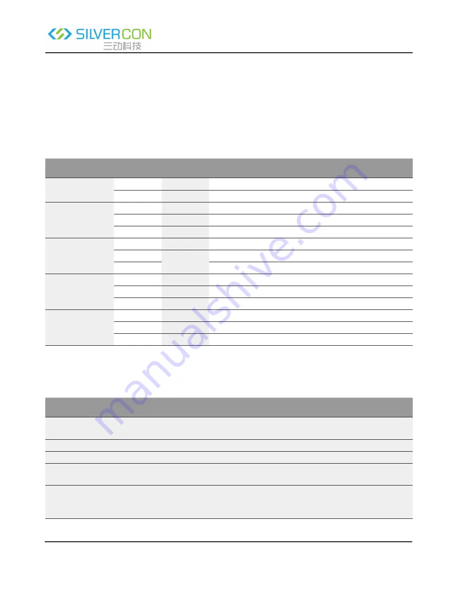
There are 8 LED indicators on the front panel of the wireless router. By observing their status, you can check
whether the device runs normally.
The following table describes the status of LED indicators on the front panel.
Indicator
Color
Status
Description
Power
Green
On
Power is on.
-
Off
Power is off or the device is down.
WLAN
Green
On
Radio switch is turned on.
Green
Blink
Data is being transmitted.
-
Off
Radio switch is shut off.
WPS
Green
On
Connection succeeds under Wi-Fi Protected Setup.
Green
Blink
Negotiation is in progress under Wi-Fi Protected Setup.
-
Off
Wi-Fi Protected Setup is disabled.
WAN
Green
On
Connection succeeds.
Green
Blink
Data is being transmitted.
-
Off
No WAN connection.
LAN1/LAN2/
LAN3/LAN4
Green
On
LAN connection succeeds.
Green
Blink
Data is being transmitted.
-
Off
No LAN connection.
3.2 Rear Panel and Interface Description
The following table describes interfaces and buttons on the rear panel.
Interface/Button
Description
Reset
Use a fine needle to press Reset gently for 3-6 seconds and then release
the button. The system reboots and restores to the factory defaults.
Power
Power socket, for connecting the power adapter.
WAN
RJ45 WAN interface, for connecting WAN or the uplink network devices.
LAN1/LAN2/
LAN3/LAN4
RJ45 LAN interfaces, for connecting hub, switch, or computer in a LAN.
WPS
This button is used for enabling WPS PBC mode. When WPS is enabled,
press this button, and the AP starts to accept negotiation of PBC mode.