background image

Operating Manual - English 


Triax QUATTRO  


- 88 - 

Copyright Silca 2011 


7.10.3 

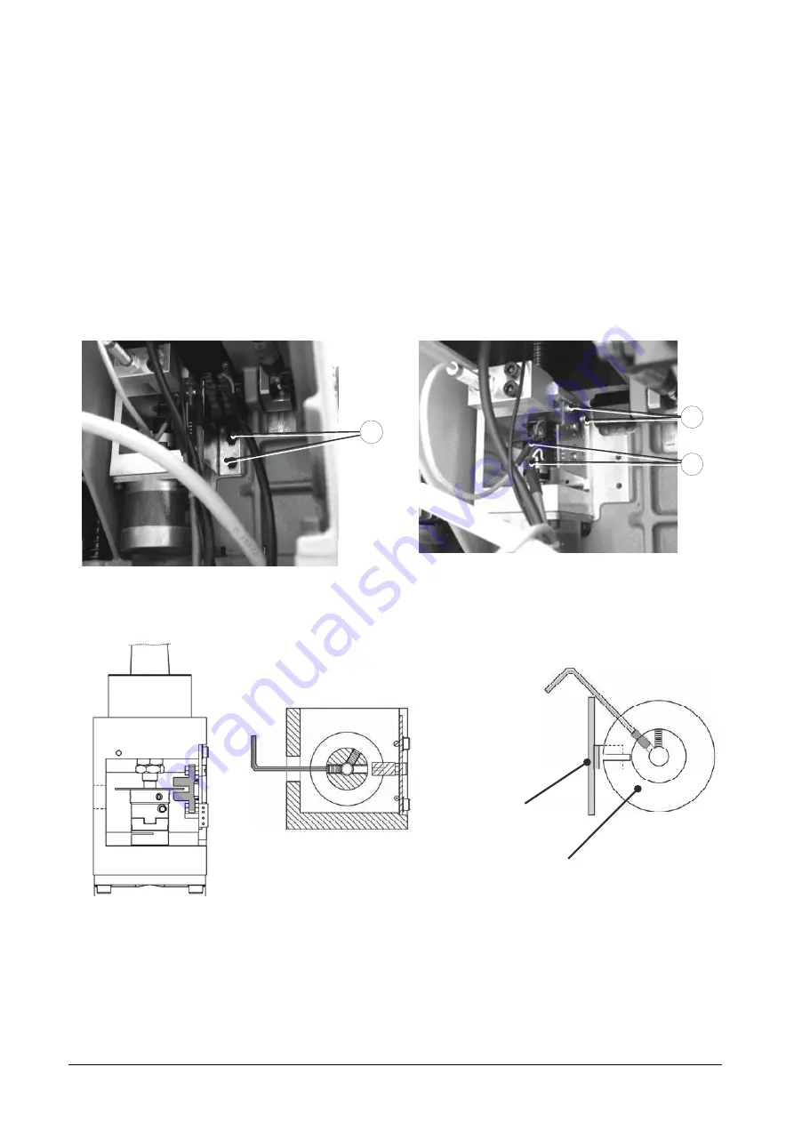
REPLACING PHOTOCELL FOR VERTICAL AXIS (Z) 

1.


Switch off the machine and disconnect the power lead. 

2.


Remove the rear metal plate (see ACCESS TO REAR). 

3.


Loosen the two screws (J1) and remove the microswitch support plate. 

4.


Disconnect the photocell and sensor cable (J3). 

5.


Loosen the 2 photocell fixing screws (J2) and remove. 

6.


Place the new photocell in position and secure with the screws (J2), connect the two cables (J3). 

7.


Replace the microswitch support plate and secure with the screws (J1). 

8.


Secure the rear metal plate. 

9.


Reconnect the power lead and Switch on the machine. 

10.


Calibrate the machine (see CALIBRATION functions). 


J1


Fig. 42 


J2

J3


Fig. 43 


REGULATION OF PHOTOCELL DISK (SEE MACHINE ZEROS) 


Photocell 

Photocell disk


Summary of Contents for Triax Quattro

Page 1: ...Operating Manual D437248XA Vers 3 0 Original Instructions Operating Manual D437248XA Vers 3 0 Original Instructions GB ...

Page 2: ......

Page 3: ...ibility for possible inaccuracies in this document due to printing or transcription errors The Manufacturer reserves the right to alter the information without prior notice except when they affect safety This document or any of its parts cannot be copied altered or reproduced without written authorization from the Manufacturer Keep the manual and look after it for the entire life cycle of the mach...

Page 4: ......

Page 5: ...APHICS 16 4 MACHINE DESCRIPTION 17 4 1 REGULATION AND USE 17 4 2 USING THE R1 R12 CLAMP 18 4 3 FITTING THE CLAMP TO THE MACHINE 20 4 4 USING THE CUTTERS 21 4 5 CHANGING THE CUTTER DECODER 22 4 6 USING THE USB PEN 23 5 OPERATING GUIDE 24 5 1 MACHINE KEYPAD AND FUNCTION BUTTONS 24 5 2 PRELIMINARY OPERATIONS 25 5 3 SEARCHES 26 5 3 1 SEARCH BY MAKE 27 5 3 2 SEARCH BY CODE KEY BLANK AND DESCRIPTION 27 ...

Page 6: ...BRATION FUNCTIONS 50 5 10 1 CLAMP CALIBRATION 51 5 10 2 CUTTER CALIBRATION 52 5 10 3 ADAPTER CALIBRATION 53 5 10 4 AUTOMATIC CALIBRATION OF TRACER TOWER DEVICE 54 5 11 MAINTENANCE 55 5 11 1 SPINDLE TEST 55 5 11 2 AXIS MOTORS TEST 55 5 11 3 DIGITAL INLETS TEST 55 5 11 4 DIGITAL OUTLETS TEST 56 5 11 5 KEYPAD TEST 56 5 11 6 DISPLAY TEST 56 5 11 7 SERIAL PORT TEST 56 5 11 8 MACHINE ZEROS 57 5 11 9 ARC...

Page 7: ... 85 7 10 PHOTOCELL REPLACEMENT 86 7 10 1 REPLACING PHOTOCELL FOR LOWER AXIS Y 86 7 10 2 REPLACING PHOTOCELL FOR UPPER AXIS X 87 7 10 3 REPLACING PHOTOCELL FOR VERTICAL AXIS Z 88 7 11 ELECTRONIC CIRCUIT BOARD REPLACEMENT 89 7 12 MOTOR CIRCUIT BOARD REPLACEMENT 90 7 13 CHECKING AND REGULATING SAFETY MICROSWITCHES 91 7 14 SAFETY MICROSWITCH REPLACEMENT 92 7 15 U102TT U103TT DECODING DEVICE REPLACEMEN...

Page 8: ......

Page 9: ...SERS This manual must be used by personnel assigned to the machine after having read and understood its contents MANUFACTURER ID Triax QUATTRO has an ID plate on the back of the machine showing its serial number HOW TO APPLY FOR AFTER SALES SERVICE Silca provides purchasers of Triax QUATTRO with after sales service To ensure total safety for the machine operator all operations not specified in thi...

Page 10: ...graving Clamp R2 R3 Optional clamps for special systems locks System lock Means the set of information pertaining to the key to be cut E g see examples in symbol table below Each dot represents one cut the number of dots corresponds to the number of cuts on the key Tracer Tower A Silca invention comprising a tower system for holding commonly used tracer points for decoding keys on Triax QUATTRO Us...

Page 11: ...lustration of the most frequently used terms KEY TERMINOLOGY GENERAL 6 7 1 2 3 4 5 7 Fig 1 8 Fig 2 1 Head 2 Neck 3 Stop 4 Stem 5 Tip 6 Back 7 Cuts 8 engraving area KEY TERMINOLOGY SOFTWARE SSN Silca Serial Number Fig 3 SSN Silca Serial Number Fig 4 AXIS1 AXIS2 STOP A C B D Side A 1st flat side Side B 1st back Side C 2nd flat side Side D 2nd back ...

Page 12: ...istons pins L Indicates that the main row of pistons is on the left hand side of the key R Indicates that the main row of pistons is on the right hand side of the key P Number of pistons pins per axis row T Number of Laser grooves W Number of blades pf For example pf 121 indicates original profile 121 are registered trade marks GRAPHICS ON MACHINE DISPLAY SSN e g 16 Silca Serial Number e g 8 8 Max...

Page 13: ... sign highlights the electrocution hazard from direct indirect contact with electrical voltage ATTENTION DANGER PARTS IN MOTION Attention Danger Parts in motion This sign indicates that there may be dangerous moving parts in motion PROHIBITION SIGNS OBLIGATION Prohibition sign Obligation to read the manual ...

Page 14: ...omply with current standards Silca S p A has also experimented and applied many technical solutions that allow its key cutting machines to optimize the quality of the cut keys To ensure these results over time observe the following instructions Observe the procedures described in this manual Use only Silca Original Tools as they are designed to achieve the best performance of the Triax QUATTRO and...

Page 15: ...ty in such cases RESIDUAL RISKS The Triax QUATTRO machine has residual risks in the highlighted area Fig 4 1 SAFETY REGULATIONS Always disconnect the machine when it is not in use or when maintenance is to be carried out Periodically check the electrical wiring if the wires are worn replace them immediately Always make sure your hands are dry and not oily or greasy Never pull the power lead make s...

Page 16: ...ver C Tracer Tower lever D spindle E cutter F clamp R1 R12 G upper carriage H lower carriage I display J keypad K emergency button L IN OUT port M B axis N upper axis connector O USB port for PC P serial port for PC Q USB PEN holder R tool holder S clamp knob T vertical carriage U lamp V safety shield W vacuum system connector X power socket Y fuse holder Z ON OFF switch Z1 Belt cover Y X Z W Fig ...

Page 17: ...key 13 mm spanner 4 Amp delayed fuse D908726ZR 1 5 mm hex key 2 5 mm T shaped hex key 6 3 Amp delayed fuse D910652ZR Z4 serial test receptacle D916661ZR SILCA ENGRAVING PROGRAM CD 8 Amp delayed fuse D917515ZR Calibration template Z5 W146 cutter D734267ZB 146 5 Amp delayed fuse 120V D917042ZR W101 cutter D709238ZB Adhesive to attach to safety shield ATTENTION DANGEROUS MOBILE PARTS W500 cutter D738...

Page 18: ...xes with ball screws activated by step motors on rectified roller guides Clamp R1 R12 universal interchangeable for securing keys engraving Runs lower axis Y 57 mm upper axis X 32 mm vertical axis Z 30 mm Dimensions width 450 mm depth 600 mm height 510 mm with shield raised 680 mm Mass 51 5 kg Noise rating sound pressure Lp A dB A 77 cutting steel keys brass dimple keys Leq A dB A 68 2 nickel silv...

Page 19: ...tter and signals that the shield has not been lowered with a special message on the machine display To activate the work cycle close the shield and press the START key on the machine keypad EMERGENCY STOP In the event of malfunctioning or a hazard for the operator the machine can be stopped immediately by pressing the red emergency button on the right hand side When the cause of the emergency has ...

Page 20: ... on which the machine stands and is secured and a cardboard cover The machine is secured to the base with screw brackets that stop the load from sliding during transport which could damage the safety shield in particular When the packing is closed it is held by two straps that tie the cardboard box firmly to the pallet The symbols on the outside of the cardboard box give transport instructions ATT...

Page 21: ...en the screws fixing the front and rear brackets holding the machine to the pallet 4 Use the special key to loosen the nuts on the feet by a couple of turns 5 Remove the metal brackets and tighten the nuts on the feet 6 Check the contents of the packing Triax QUATTRO key cutting machine Machine documentation operating manual spare parts list expert guide and warranty form Power lead Tool box ...

Page 22: ... Once removed from the packing place Triax QUATTRO directly on a workbench the operation should be carried out by at least 2 persons ATTENTION when lifting the machine take hold of the base only Fig 7 Never lift the machine by holding onto the keypad support Fig 8 SI Fig 7 NO Fig 8 YES ...

Page 23: ...ters are important environments with high humidity and poor air circulation are not advisable The optimum environmental conditions for the machine are temperature 10 C to 40 C relative humidity approx 60 3 3 POSITIONING Follow the procedure described below 1 Place the key cutting machine on a horizontal work bench solid enough to take its weight 51 5 Kg and big enough to allow comfortable access t...

Page 24: ...isplay 5 Emergency button 3 5 GRAPHICS Adhesive labels on the Plexiglas safety shield 1 Do not use compressed air Divieto di usare aria compressa per operazioni di pulizia 2 ATTENTION DANGEROUS MOBILE PARTS Available on the accessories provided It is obligatory to apply it to the left hand side of the machine safety shield see Fig 10 ATTENZIONE PARTI MOBILI PERICOLOSE Fig 10 It is forbidden to rem...

Page 25: ... see Fig 18 4 1 REGULATION AND USE ATTENTION to ensure that the Z axis works properly the calibration plate must be kept constantly clean with the brush provided in order to avoid pollution by swarf A false contact due to swarf will produce a Z cut depth of the wrong measurement ATTENTION ELIMINATE SWARF FROM THE CALIBRATION PLATE AND CLAMP ATTENTION do not apply too much pressure to secure the ke...

Page 26: ...e required clamp R1 or R12 position is reached close the grip A6 The R1 R12 clamp comes with a fixed plate A2 on top a mobile jaw in the centre A3 and a mobile jaw on the right A4 which can be replaced when worn The clamp is also provided with 2 calibration plates A1 for the Z axis sprung one for R1 and one for R12 which the cutter uses to home itself at the beginning of the cutting or engraving p...

Page 27: ... to close the jaws A3 and A4 and secure the object key or medal to be engraved On top of the 2 jaws on the R12 clamp there are positions numbered 0 to 8 which are used as a reference and aid the operator in positioning the key or medal to be engraved Cutter to use for engraving W146 ATTENTION the keys and medals must be metal Engraving cannot be carried out on other materials wood paper ceramics e...

Page 28: ...mp loosen the handle A9 Fig 19 and pull the clamp out of the dovetail guide To fit the clamp to the machine insert the clamp into the dovetail guide push all the way in and lock by turning the knob The instructions refer exclusively to the clamp provided To use any optional clamps follow the instructions provided with them A9 Fig 19 ...

Page 29: ...e shown on the display The type of cutter to fit is indicated by the letter W hard metal If the operator does not have the required tool s he may select a different one indicated by the letter W hard metal see page 32 User Parameters indicated by the letter H HSS if included in the Silca database see CUTTER CALIBRATION It is good practice to set the cutter material for your cutters In this way whe...

Page 30: ...wn B1 Fig 20 and turn anticlockwise until the tool is released Remove the tool To fit a tool proceed as follows Block spindle rotation by lowering the lever B2 Fig 20 Fit the tool into spindle and push all the way in Hold the tool in place with one hand and with the other lower and turn the knob B1 Fig 20 clockwise Release spindle rotation by raising the lever B2 Fig 20 ATTENTION when commencing a...

Page 31: ... of the following ways PROCEDURE 1 With the key cutting machine off the USB PEN can be removed or inserted 2 With the key cutting machine on the USB PEN must be disabled This operation is possible from the main menu with numerical key 2 or from the sub menus where a USB pen icon appears function button USB pen status goes to OFF and the luminous LED on the pen goes off USB PEN Fig 21 ...

Page 32: ...e video screens once the data have been transmitted 5 1 MACHINE KEYPAD AND FUNCTION BUTTONS Tasto funzione Tasto MENU Tasto freccia Fig 22 The MENU button shows a list of the main functions The MENU button is always active from any window Function buttons F1 F2 F3 F4 select the options shown on the screen Arrow keys right left up down are used to navigate in the fields on the screen CLEAR button u...

Page 33: ...ing unit default is MILLIMETRES 6 When the machine is switched on the following MAIN SCREEN appears on the display The main screen shows the Function icons as well as the following data Name of key cutting machine Machine serial number SW version machine program version DB version Series database version on machine MENU wording flashing Date Time ON Press button 1 to enable the USB PEN OFF Press b...

Page 34: ...rds created by the user F1 F2 F3 F4 F1 to access the Search menu F1 F2 F3 F1 to change the search field possible search modes SSN Make Code Key blank Description F4 F1 F2 F3 F2 to enter List of Favorite Series A list of frequently used series from which to make a rapid choice This list must be created by the user see Ch 5 5 6 F4 F1 F2 F3 F3 to enable or disable the USB PEN N B Searches by code tab...

Page 35: ...e machine database 5 8 4 4P 1 200 description of series provided by SILCA The top window shows other information about the selected series Press ENTER to confirm and enter in the required Lock System SSN 5 3 2 SEARCH BY CODE KEY BLANK AND DESCRIPTION Enter the known parameter into the relative field and press ENTER A list will appear scroll with the arrow keys until you select the required series ...

Page 36: ...and enter into the selected Lock System SSN Description graphics in Table 2 F1 F2 F3 F1 Key decoding function F2 Engraving function F3 Indirect Code Entry if applicable F4 to access other Functions see Ch 5 5 F4 F1 F2 F3 F1 to add the system used to the Favorite Series List F2 to view the key parameters in relation to the current axis F3 to access the User Parameters menu F4 ...

Page 37: ...amp Place the original key in the clamp with the key stop up against the STOP position Lower the shield and press START When decoding is finished the display will show a new window with 4 columns giving from left to right FUNCTION BUTTONS after Decoding F1 F2 F3 F1 to scroll the key axes and view the values obtained by decoding F2 to cut the key using the measurements read decoded In this case you...

Page 38: ...e current type of key Side and axis Side and axis to be cut Cuts Combination of cuts on the side and axis selected Cutter Cutter to use for cutting the side and axis selected Pieces Number of keys to be cut N B If the cutter and or clamp required are not available press F2 to check whether the selected cutting system provides other possibilities Key cutting PROCEDURE Raise the safety shield Remove...

Page 39: ...e axis shown Cuts field for entering cuts for the axis shown Depth symbols and values Symbols for depths admitted with relative values 1 100 mm for the axis shown Pieces Number of keys to cut PROCEDURE for entering cuts With the cursor in the cut field use L H R H arrow key to skip a position Up down arrow key to change cutting axis CLEAR button to delete the value entered cursor to the far left d...

Page 40: ...down arrow keys to scroll the list select the required series and press ENTER F1 F2 F3 F1 for Manual adjustments F2 for User parameters F3 for Code entry see Ch 5 5 F4 INDICATIONS on display and key cutting PROCEDURE The code in use is shown next to the window header SSN 16 1 At the end of the cutting operation press F3 to enter a new code For the full cutting flow see paragraph 5 4 2 1 ...

Page 41: ... 0 Negative value of Y takes cut away from STOP 0 Positive value of Z makes cut deeper Negative value of Z makes cut less deep Adjustment values for X Y Z 30 to 30 hundredths of mm NOTIFICATION OF VARIATION This flashing warning symbol appears inside the Manual Adjustment icon only when manual adjustments have been entered 5 5 2 USER PARAMETERS This function is used to select a clamp or cutter alt...

Page 42: ...gin cutting When cutting is complete press F3 to enter a new code 5 5 4 DECODING DATA Function active after decoding Shows the data obtained from the last decoding operation 5 5 5 ENGRAVING FROM CURRENT SSN This function is used to go to the engraving mode If an engraving template has been associated to the current SSN it will appear as selected F1 F2 F3 F1 to go from Silca templates to User templ...

Page 43: ...GRAVING F1 F2 F3 F2 to associate the current engraving template to the SSN in use The same button can also be used to disconnect the current engraving template from the SSN in use F4 A special icon indicates that an engraving template has been associated to the current SSN The advantage of this association F4 to proceed with engraving the associated template after completing the key cutting cycle ...

Page 44: ...series in the list CLEAR numerical buttons 1 to 0 to eliminate a Series from the list 5 5 7 VIEW SERIES AXIS PARAMETERS F1 F2 F3 From the system in use access can be gained to the function with F2 The parameters relative to the cuts in the SSN in use are shown F4 Available 1 Parameters referring to the key stem length width and thickness 2 Name of cutter to use with angle and base of cut parameter...

Page 45: ...his case the SSN selected for decoding is not compatible with the decoded key Example Enter SSN 681 Press ENTER Enter cutting data FAAFFF Press ENTER The Silca software calculates the validity of the data entered or decoded If there is an inconsistency the following message appears COMBINATION NOT ALLOWED 5 6 2 DECODING NOT ALLOWED N B IT IS NOT POSSIBLE to decode anodized aluminium keys plastic k...

Page 46: ...er the number and press ENTER The following warning message may appear SSN not in the archive The message may appear when 1 The SSN entered is not in the Silca archive 2 The SSN entered is in the Silca archive but has not been enabled by the User SHIFT F3 to enable search by all makes To enable only the SSN required see Ch 5 12 3 ...

Page 47: ...the functions Press ENTER to continue See Table 2 for description of graphics To access protected data 1 apply to the manufacturer for authorization 2 communicate to Silca Key cutting machine serial number XXXXXXXXXXXXX Read the serial number on the ID plate on the back of the machine or on the initial display Machine ID XXXXX Given in the password box ENABLING Code XXXXXXXXXX Shown ONLY when acce...

Page 48: ...r notes F2 to select the first job in the queue not yet started or not fully completed due to an interruption 1 2 3 4 5 6 The data received from the PC are presented in the form of a list for example 1 number of jobs received 2 cutting codes received Silca engraving template 3 engraving jobs or a number indicating the SSN 4 number of pieces to do 5 indicates that the job HAS BEEN COMPLETED 6 indic...

Page 49: ...e 38x40 mm see fig 21 5 8 1 ENGRAVING TEMPLATE PARAMETERS The key cutting machine can be used without a PC but with certain limitations To make use of all the potential available it is advisable to use the special function included in the Triax Engraving Program see machine accessories and Silca Key Programs Engraving templates are made up of the parameters defining an engraving job No of lines Ma...

Page 50: ...fined templates i e over 200 templates relating to SILCA key blanks ready for use The following can be edited but not saved in the machine memory contents of the lines of text material thickness engraving depth X X Creation of User templates X Use of User templates X X Transferred by SKP to a special archive on the machine Editing user templates X X Limited to contents of lines of text material th...

Page 51: ...rameter for the engraving template then descends by a distance given in the set depth parameter A ELECTRIC CONTACT POSSIBLE on material to be engraved N B it is better to set the thickness value slightly lower than nominal read by a centesimal gauge to assist reading the measurement by electric contact Example if the item to engrave has a thickness of 2 00 mm 200 hundredths of mm it is better to s...

Page 52: ...F2 F3 F3 F4 F4 Button F2 views the position and size of the text area on the selected template The values shown cannot be edited for SILCA templates F1 F1 F2 F2 F3 F3 F4 F4 For user templates only the following values can be edited Dx X coordinate of the top L h vertex see machine display above Dy Y coordinate of the top L h vertex see machine display above Width width of line or area of text Heig...

Page 53: ...phanumerical keys Up and down arrow keys to move the cursor between the 2 lines Press ENTER Side front 1 back 2 engraving side Reference reference for key engraving 0 Clamp name of clamp to use Cutter name of cutter to use Thickness key or medal thickness 100 mm Depth engraving depth 100 mm Pieces number of pieces to do In the Thickness Depth and Pieces jobs fields the value can be edited Pay atte...

Page 54: ...Name of template IE 14 Text to enter 1 SILCA 2 SPA 3 F1 F1 for counter function 3 F1 see Ch 5 8 5 1 1 N B Use only alphanumerical keys to edit the text Up and down arrow keys to move the cursor between the 3 lines Press ENTER Side front 1 back 2 engraving side Reference reference for key engraving 0 Clamp name of clamp to use Cutter name of cutter to use Thickness key or medal thickness 100 mm Dep...

Page 55: ...ue 100 finale value of counter Increase 1 step increase of counter Check all the counter values then press STOP Prepare the key cutting machine for engraving in the way described on the display Press START to begin engraving Example With the Pieces value set above 1 the third line of the text will show on the counter the numerical value to engrave Example In the next jobs the numerical value to en...

Page 56: ... Series User engraving templates Scroll with the up down arrow keys to select the required field Machine software F1 F2 F3 Check that the version on the USB PEN is more up to date than the version on the machine Press ENTER When the machine is being updated the display will go off for a few seconds and then come back on Wait until data downloading is finished The machine will restart from the init...

Page 57: ...iew User engraving templates on the USB PEN F2 to view User engraving templates on the machine F1 F1 F2 F2 F3 F3 ATTENTION When Engraving templates are downloaded from a USB PEN all the user engraving templates already on the machine are lost Only the user engraving templates on the USB PEN are downloaded ...

Page 58: ...LIBRATION In the events shown in the table it may be necessary to repeat one or all the calibration operations on the clamps in your possession This operation is semi automatic and requires careful attention to the instructions below These adjustments must be made when the following events occur CALIBRATION TABLE EVENT CLAMP calibration TRACER TOWER calibration Photocell replacement YES YES Electr...

Page 59: ...R the display will show the message on the right here Make sure tracer point U103 is fitted N B Carefully clean the clamp and calibration plate ATTENTION ELIMINATE SWARF FROM CALIBRATION PLATE AND CLAMP Press START to proceed with calibration When calibration is finished the display shows the differences in the values read Calibration will be accepted only if the size of the variations is between ...

Page 60: ...utter calibration function F4 CUTTERS do not need an automatic calibration system N B the type of material and length can be edited where applicable it is good practice to set the type of material for the cutters in your possession In this way spindle speed will be appropriate for the cutter required by the SSN in use ...

Page 61: ...values F2 for negative values F3 to delete the adjustments made F4 Positive value of Y takes cut closer to stop Negative value of Y takes cut away from stop Positive value of X moves cut to the right of the axis Negative value of X moves cut to the left of the axis Positive value of Z lowers the cut from the axis Negative value of Z raises the cut from the axis Adjustments to Spaces Depths Heights...

Page 62: ... for cutting the key The machine program is prepared to perform calibration and decoding with either the TRACER TOWER or a tracer point fitted in the place of the cutter Simply enable or disable the TRACER TOWER from the OPTIONS menu The TRACER TOWER must be CALIBRATED before use The TRACER TOWER calibration procedure is carried out only with clamp R1 already calibrated Manual adjustments and sett...

Page 63: ...he spindle is on e g RPM Volt C F4 to view the information about the spindle motor activation card to send to Silca if required F4 5 11 2 AXIS MOTORS TEST Follow the instructions on the display and check that the carriage for the axis in question moves X Y Z Axis B optional clamp R13 N B During these tests all the limit switch controls are disabled take care not to take the carriage up against the...

Page 64: ...ptional devices fitted 5 11 5 KEYPAD TEST Press all the buttons one at a time except STOP and check on the display that the same circled button appears for each button pressed Press the STOP button last to quit the test 5 11 6 DISPLAY TEST Press ENTER a number of times to check that the background colour changes Press STOP to quit the test 5 11 7 SERIAL PORT TEST Check that the indication on the d...

Page 65: ...ve back plate 3 Loosen the grub screws securing the photocell disk for Y G and Z L axes 4 Remove bottom plate 5 Remove the X axis carriage cover by loosening the 3 screws B5 and pull out in the direction given then remove the belt cover 6 Loosen the grub screws securing the X axis photocell disk 7 Reconnect the power lead 8 Switch on the machine and follow the procedure described below N B the ope...

Page 66: ...calibration pin 6x40mm in its place make sure it is pushed all the way up to the mechanical stop Press ENTER Check that the template Z5 and calibration pin are in the position shown in Fig 23 Lower the safety shield and press START Z5 Fig 23 The machine takes the axes into the predefined position ...

Page 67: ...e the hex key to loosen the grub screw H7 slowly move the rod H6 manually in both directions until you find the point at which it goes from OFF to ON Secure the rod by tightening the grub screw H7 Lower carriage Y sensor tip the machine onto its side Loosen the sensor plate fixing screw E4 and move the plate manually until the description on the display goes from OFF to ON Fix the plate by tighten...

Page 68: ...edited data The previous values remain valid already in the machine memory N B If the calibration values read exceed the limits allowed an error message will appear Repeat the Machine Zeros procedure more carefully ENTER to confirm the MACHINE ZEROS procedure All the clamps in your possession must be re calibrated ...

Page 69: ...G file can be sent to the After Sales Service so any problems when operating the key cutting machine can be better understood When using SILCA or User series the operator can edit some of the parameters such as the cutter clamp manual adjustments etc The EXPORT PARAM function can be used to save these parameters on the USB PEN as a backup copy and load them onto the machine memory with the IMPORT ...

Page 70: ...illimetres inch inches then press ENTER to confirm Quick menu if enabled YES used in heavy operating flows to skip some of the steps and speed up the required procedure Keypad inversion function normally disabled use the arrow keys r h l h to select your choice YES or NO then press ENTER to confirm This operation is used to invert the function of the alphanumerical keys Keypad inversion disabled t...

Page 71: ...ilters F4 to enable or disable all makes Press CLEAR to cancel the selection 193 total number of makes 4 193 partial number of makes selected by user The standard machine setup enables searches through all makes as soon as one is selected F4 5 12 4 MACHINE OPTIONS PAGE 4 4 The display shows Clock Date and time formats use the arrow keys r h l h to select the format required for the DATE DD MM YY b...

Page 72: ...ction List of protected systems already enabled They can be protected again Use the arrow keys up and down to select the protected system already enabled F1 to protect the SSN again The display shows another message requiring confirmation of removal STOP to quit the operation without editing ENTER to confirm After confirmation the display will show ...

Page 73: ...n indirect code is needed to access the series Do you want to proceed No STOP Yes ENTER ATTENTION The jaw is not calibrated By pressing ENTER you can only consult the cards data The messages warn the user that to cut a key with this series a different clamp must be fitted or the clamp involved must be calibrated This operation must be performed before using the series Press ENTER to consult the se...

Page 74: ...the SKP program or the Free Engraving program provided with the machine ATTENTION This operation will overwrite all User models previously saved in the machines memory Not to lose any changes made to the User templates please use the Silca Key Programs to transfer the engraving models The text inserted on the LINE shown at the end of the message is outside the set rectangle or area Reduce the numb...

Page 75: ...and activated The required data have not been found on the USB PEN check that the pen is connected and contains the data If the contents of the USB PEN have been deleted by mistake use the WinTransfer SRS program to re load the data by means of the special function ATTENTION Data not found or USB PEN not inserted 6 1 2 MESSAGES LINKED TO PRESENCE OR USE OF MOTORIZED CLAMP ATTENTION Jaw replacement...

Page 76: ... ERROR 1 Depth limit exceeded The machine automatic calibration procedure has read adjustment values exceeding the tolerance established by SILCA Repeat the procedure and pay attention to all the operations required If the problem persists contact After Sales Service ERROR 2 Tolerance limit exceeded during calibration Repeat the operation See operating manual The spindle rotation release lever is ...

Page 77: ... long offcut is creating a bridge between the tool and the fitted key clean all the swarf off the machine and repeat the operation An offcut is creating a bridge between the TRACER TOWER and the machine carefully clean any swarf off the TRACER TOWER ERROR 7 Faulty contact made Press START to reset axes Check that the fitted tool is the one required for the operation in progress the length of the t...

Page 78: ...red in calculating the engraving path Make a note of the error and the condition which caused it and advise After Sales Service ERROR 13 Error in calculating engraving process Code Error in loading data onto the machine with the USB PEN Please repeat the operation to reload the data onto the USB PEN If the error persists make a note of it and the condition which caused it and advise After Sales Se...

Page 79: ... motorized clamp cable with the machine on is very dangerous because it could damage the electronic circuit board IMPORTANT To fit a motorized clamp for example the R13 tilting clamp carry out the procedure below Switch off the machine Fit the motorized clamp Connect the special cable to connector B on the right hand side of the machine Switch on the machine ERROR 15 OPERATION NOT ALLOWED Jaw not ...

Page 80: ...achine The message indicates faulty functioning of the axis involved in the clearing procedure Clearing sensor or photocell not working Repeat the operation a number of times If the problem persists contact After Sales ALARM 9 Axis movement not completed during resetting phase This message appears when an application on the PC tries to transfer data to the machine in the wrong format Check whether...

Page 81: ...LARM 5 SPINDLE DRIVER ALARM No communication between mother board and spindle drive See operating manual Effect Motor not turning Cause Short circuit on spindle motor or board power loss Driver damaged Check AZ motor board connectors ALARM 6 SPINDLE DRIVER ALARM Spindle speed not detected motor locked See operating manual Effect Free running motor does not reach the rotation speed required for cut...

Page 82: ...Triax QUATTRO 74 Copyright Silca 2011 1 Generic alarm relating to the spindle driver board If the problem persists contact After Sales Service ALARM 4 SPINDLE DRIVER ALARM Code 00000000 See operating manual ENTER to reset alarm ...

Page 83: ... special maintenance but it is good practice to check and if necessary replace parts subjected to wear and substitute electric electronic parts fuses circuit boards etc when they are not working properly Parts can be replaced by the operator observing the instructions N B For normal maintenance of burnished mechanical parts we suggest using lubricants or protective products such as WD40 or similar...

Page 84: ... or the connectors are not inserted properly Display shows the words Cutting or decoding in progress etc but the X Y Z axes are not moving and no buttons are enabled Electronic circuit board faulty a the closed safety shield is not touching the microswitch properly The display shows the message close safety shield when it is already closed b fuse F4 on the control circuit board cut out a the keypa...

Page 85: ...e display shows the message TEMPERATURE ALARM Switch off the machine Check that the fan on the back of the machine is working working a control circuit board faulty Use tests digital inlets to check the photocell sensor Check fuse F4 on the circuit board Check the X axis connecting wire J1 The X axis upper carriage moves to the left or right and knocks against the machine limit switch Control circ...

Page 86: ...gerous position for the operator 1 Turn off the master switch and disconnect the power lead 2 Loosen the 3 screws and remove the belt cover tightening increase tension on the belt by loosening the 4 screws C1 C2 C3 C4 with the Allen wrench provided and pushing the pulley back Tighten the 4 screws replacement remove the belt and replace 3 Replace the belt cover and secure with the 3 screws C1 C2 C4...

Page 87: ...lead 2 with the aid of a screwdriver open the socket flap remove the fuses and replace if necessary Fig 25 3 fuses F2 F3 F4 F2 6 3 Amps delayed Protect the step motors and their electronic controls 32V d c F3 4 Amps delayed Protect the logic circuits for controlling the microprocessor circuit board 5V d c F4 2 Amps delayed Protect the digital outlet circuits for the low voltage controls and sensor...

Page 88: ...yed 100V 120V Protects the main electronic circuit board transformer Situated in the bottom of the base F5 2 fuses F6 F7 1 fuse F6 8 Amps delayed Protects motor power 1 fuse F7 315mA delayed Protects the motor circuit board Situated on the motor circuit board at the rear of the base Motor circuit board F7 F6 ...

Page 89: ...nd disconnect the power lead 2 Loosen the 2 fixing screws F1 and remove the display stand 3 Detach the cable and earth wire from the keypad 4 Loosen the keypad fixing nuts and remove the keypad from its stand 5 Fit the new keypad display by repeating the operations described above in reverse order F1 Fig 26 Fig 27 Fig 28 ...

Page 90: ...e machine and disconnect the power lead 2 loosen the 6 screws B1 fixing the back metal plate and remove B1 Fig 29 7 8 ACCESS TO BOTTOM PART To access the bottom part of the machine follow the instructions below 1 switch off the machine and disconnect the power lead 2 turn the machine onto its back 3 loosen the 8 fixing screws D1 and remove the bottom metal plate D1 Fig 30 ...

Page 91: ...nect the lower Y axis sensor connector from the circuit board ATTENTION DO NOT LOOSEN SCREW E4 7 loosen the nut E 3 unscrew the sensor from the plate and remove Fig 31 8 loosen the 3 screws E1 Fig 32 and remove the lower carriage front cover 9 place the new sensor in position and screw down until it almost touches the screw E2 then lock the nut E3 10 connect the sensor connector to the circuit boa...

Page 92: ...e sensor connector G3 from the circuit board 5 Loosen the nut G1 unscrew the sensor from the plate and remove 6 Place the new sensor in position screw down until it almost touches the pin G4 and secure with the nut G1 7 Connect the sensor connector to the circuit board 8 Replace the rear metal plate and belt cover G2 G1 G3 Fig 33 Drawing references for SENSOR REPLACEMENT AND REGULATION see MACHINE...

Page 93: ...and pull out in the direction given 5 Disconnect the sensor connector H4 6 Loosen the grub screw H5 with the allen wrench provided 7 Remove the faulty sensor H3 and place the new sensor in position until it almost touches the pin below H6 and tighten the grub screw H5 8 Connect the sensor connector H4 9 Replace the upper axis carriage cover 10 Connect the upper axis cover cable H2 to the carriage ...

Page 94: ...lead 2 Remove the rear metal plate see ACCESS TO REAR COMPARTMENT 3 Loosen the 2 photocell fixing screws I1 and remove 4 Disconnect the photocell cable I2 5 Connect the cable to the new photocell 6 Place the photocell in position and secure with the screws I1 7 Calibrate the machine CALIBRATION FUNCTIONS I2 I1 Fig 39 REGULATION PHOTOCELL DISK see MACHINE ZEROS Photocell Photocell disk ...

Page 95: ... the direction given 4 Disconnect the photocell cable H6 and sensor cable H3 5 Loosen the screw H8 6 Loosen the 2 screws H7 on the photocell support and pull out of carriage 7 Place the new board in position on the carriage and tighten the 2 support screws H7 8 Connect the photocell cable H6 and sensor cable H3 9 Connect the upper axis connection wire H2 to the carriage 10 Calibrate the machine CA...

Page 96: ...isconnect the photocell and sensor cable J3 5 Loosen the 2 photocell fixing screws J2 and remove 6 Place the new photocell in position and secure with the screws J2 connect the two cables J3 7 Replace the microswitch support plate and secure with the screws J1 8 Secure the rear metal plate 9 Reconnect the power lead and Switch on the machine 10 Calibrate the machine see CALIBRATION functions J1 Fi...

Page 97: ...connect all the wires from the circuit board 4 Loosen the nuts N1 and remove the circuit board 5 Fit the new board onto the threaded pins and tighten the nuts N1 6 Connect all the wires each connector is polarized and its position cannot be changed 7 Close the bottom compartment 8 Carry out the calibration operations see MACHINE ZEROS CLAMP AUTOMATIC CALIBRATION OF TRACER TOWER DEVICE N1 Fig 44 ...

Page 98: ...ss the rear compartment 3 Disconnect all the wires from the circuit board connectors 4 Loosen the 3 fixing screws M4 5 Remove the circuit board and replace with a new one 6 Tighten the three fixing screws M4 7 Connect all the wires to the circuit board connectors each connector is polarized and its position cannot be changed 8 Close the rear compartment M4 Fig 45 ...

Page 99: ... 3 Check that the Digital Inlets Cover Micro test is successful If not check that the cam J6 makes the two microswitches click If necessary regulate the cam as follows 4 Remove the belt cover and lower the safety shield V 5 Use the 2 5mm T wrench to loosen the grub screw J5 6 Hold the wrench in the seat for the grub screw J5 turn the cam J6 until the microswitches click J1 J4 Fig 46 J6 J5 Fig 47 ...

Page 100: ...switches J4 4 Loosen the two nuts J7 and replace the faulty part 5 Secure the microswitches with the two nuts and connect the two wires the wire marked SX on the left and the wire marked DX on the right 6 Replace the microswitch support plate with the screws J1 without tightening them 7 Adjust the position of the plate so that when the safety shield V is moved the microswitches click 8 Secure the ...

Page 101: ...ER TOWER 1 Loosen the screw K1 or K2 according to the decoder to be replaced 2 Remove the broken decoder from its seat 3 Place the new decoder in the seat and align with the top part of the TRACER TOWER 4 Tighten the screw K1 or K2 according to the decoder to be replaced 5 Calibrate the Tracer Tower K1 K2 F3 Fig 49 ...

Page 102: ...TTERY REPLACEMENT Replacing the battery is a simple operation but must be carried out with care 1 Disconnect the power lead from the key cutting machine 2 Gain access to the bottom compartment 3 Use pliers with insulated tips to grip the battery and pull it out taking care to push towards the pressure tab to remove from its shaped housing 4 Use the pliers with insulated tips to introduce the new b...

Page 103: ... by current laws in Italy and the European Union If it is contaminated or contains harmful noxious substances which transform the metal residue included in SUW into harmful noxious substances it is included in the lists of the appendices to current regulations in Italy and the European Union for waste disposal INFORMATION TO USERS Under the terms of art 10 of Directive 2002 96 CE dated 27 01 2003 ...

Page 104: ...y the manufacturer or in the special Service Centres recommended by Silca On the back cover of the manual there is a list of the manufacturer s addresses the following page lists the addresses of specialized Service Centres 9 1 HOW TO APPLY FOR AFTER SALES SERVICE The warranty attached to the Triax QUATTRO machine guarantees free repairs or replacement of faulty parts within 24 months of purchase ...

Page 105: ...Triax QUATTRO Copyright Silca 2011 I Allegato Appendix 1 SCHEMI ELETTRICI ELECTRICAL DIAGRAMS ELEKTRISCHE SCHALTPLANE SCHEMAS ELECTRIQUE ESQUEMAS ALAMBRICOS ESQUEMAS ELÉCTRICOS ELEKTRISCHE TEKENINGEN ...

Page 106: ...Triax QUATTRO Copyright Silca 2011 1 II ...

Page 107: ...Triax QUATTRO Copyright Silca 2011 III ...

Page 108: ...Triax QUATTRO Copyright Silca 2011 1 IV ...

Page 109: ...Triax QUATTRO Copyright Silca 2011 V ...

Page 110: ...Triax QUATTRO Copyright Silca 2011 1 VI ...

Page 111: ...Triax QUATTRO Copyright Silca 2011 VII ...

Page 112: ...Triax QUATTRO Copyright Silca 2011 1 VIII ...

Page 113: ...Triax QUATTRO Copyright Silca 2011 IX ...

Page 114: ...Triax QUATTRO Copyright Silca 2011 1 X ...

Page 115: ...opean Directives European Union DIRECTIVE 2006 42 CE Machines and with the EN 12100 1 EN 12100 2 Standards European Union DIRECTIVE 2004 108 CE Electromagnetic Compatibility and with the EN 55022 EN 55024 EN 61000 3 2 EN 61000 3 3 EN 61000 6 2 Standards European Union DIRECTIVE 2006 95 CE Low Voltage 10 and with the EN 60950 1 EN 62233 Standards Claudio Tomasella of the Silca S p A Research Develo...

Page 116: ...0 2 22404705 gam intouch com Finland Hardware Group Finland Oy Hgf Ltd Luostarinportti 5 Kirkkonummi 02400 358 9 2219490 358 9 2962186 asiakaspalvelu hgf fi France SILCA S A S 12 Rue de Rouen B P 37 Z I Limay Porcheville 78440 33 1 30983500 33 1 30983501 info silca fr Germany SILCA GmbH Siemensstrasse 33 Velbert 42551 49 2051 2710 49 2051 271172 info silca de Greece Chrisikos K Ioannhs 7 Pipsou St...

Page 117: ...skiy Moscow 119021 7 495 7083440 7 495 7083292 Russia O O O Peter Key Mihaylovsky Pereulok 7b Saint Petersburg 198095 7 812 2520241 7 812 2523885 peterkey peterkey ru Saudi Arabia Fahd Omar Bamashmous Est P O Box 20919 Jeddah 21465 966 2 6422588 966 2 6447238 bamashmous_est hotmail com Serbia Silkon D O O 29 Novembra 70 Belgrade 11000 381 11 2080200 381 11 3290017 silkon ptt yu Singapore Silca Sox...

Page 118: ...SILCA S p A Via Podgora 20 Z I 31029 VITTORIO VENETO TV Tel 0438 9136 Fax 0438 913800 E mail silca silca it www silca biz Members of the Kaba Group ...

Reviews: