background image

2-44

Supplement

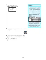
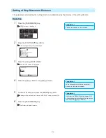
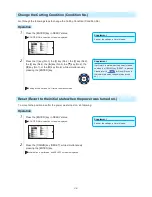
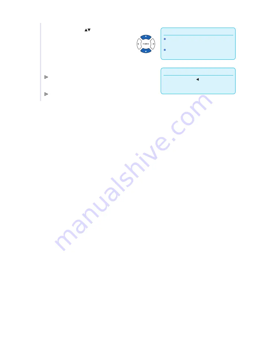
 Press the [FAST] key to change the setting 

digits.

 You can enter any digit between 20.0 and 

5000.0 cm (7.874 and 1968.504 inch).

  4 

Press the POSITION (

) keys to change the current setting.

Supplement

Press the POSITION ( ) key to return to the 
MEDIA setting screen without changing any 
settings.

  5 

Confirm the setting and press the [ENTER] key (SET).

 Setting will be set, and it will return to MEDIA SETTING screen.

  6 

Press [PAUSE/MENU] key.

 It will return to default screen.

Summary of Contents for Vinyl Express Qe6000

Page 1: ...CUTTING PLOTTER USER S MANUAL MANUAL NO VEXQe60 UM 151...

Page 2: ......

Page 3: ...ore reading the Manual DANGER This category provides information that if ignored is highly likely to cause fatal or serious injury to the operator WARNING This category provides information that if ig...

Page 4: ...o disassembly Do not connect the plotter to a non rated power supply Such action may cause electric shock or a fire hazard due to current leakage Prohibited Do not use the plotter in a location where...

Page 5: ...plotter Prohibited Do not place any receptacle containing water or other fluid on top of the plotter Fluid falling inside the plotter may cause electric shock or a fire hazard due to current leakage...

Page 6: ...pt to lubricate the cutting plotter mechanisms Such action may cause it to break down Prohibited Provide sufficient space around the plotter so that it does not strike any objects in its vicinity duri...

Page 7: ...nterparts Notes on this Manual 1 No part of this publication may be reproduced stored in a retrieval system or transmitted in any form or by any means without the prior written permission of SIGN Ware...

Page 8: ...s or other parts of your body Promptly return used blades to the cutter case provided Blade tip When the case is completely filled discard the used blades together with the case Cutter Pens The tip co...

Page 9: ...nd loaded media To prevent operator injury and poor cutting results be careful not to allow hands hair clothing or other foreign objects to become entangled with the tool carriage or loaded media whil...

Page 10: ...e protection against harmful interference when the equipment is operated in a commercial environment This equipment generates uses and can radiate radio frequency energy and if not installed and used...

Page 11: ...2 Blade Application and Features 2 3 2 2 Attaching a Tool 2 4 Attaching a Tool 2 4 Removing the tool 2 5 2 3 Loading Media Paper or Marking Film 2 6 Loading Roll Media 2 6 Loading Sheet Media 2 10 2 4...

Page 12: ...3 5 Stop Cutting 3 12 Pause and Resume Cutting 3 12 Stop Cutting 3 13 Chapter 4 Convenient Functions 4 1 Settings for Cutting 4 2 Setting Cutting Area 4 2 Setting Cutting Width EXPAND 4 4 Setting Len...

Page 13: ...er of thick media sharply 7 2 Outline of Tangential Emulation 7 2 Setting the Tangential Emulation 7 3 Setting Length of the Overcut 7 4 Setting of the Initial Down Force 7 6 7 2 Setting the Step Pass...

Page 14: ...Troubleshooting 13 2 When the Plotter Does Not Operate After Turning the Power On 13 2 When It Does Not Work Right 13 3 When the Cutting Result is Not Good 13 5 Error Messages in GP GL Command Mode 13...

Page 15: ...1 1 Chapter 1 Product Summary This chapter explains how to connect this device your computer PRODUCT SUMMARY 1 1 Checking the Accessories 1 2 Nomenclature 1 3 Assembling 1 4 Connecting to the Computer...

Page 16: ...E AND CORRECT USE 1 of each Cutter holder PHP33 CB09N HS 1 pc Cutter blades CB09UB 1 1 pc Water based fiber pen adapter PHP31 FIBER Plunger Height adjustment tool 1 set Water based fiber pen KF700 BK...

Page 17: ...or plotting Tool holder Holds the cutter pen or plotting pen and moves it up or down Grit roller position guide Stickers on the front of the Y rail and the rear side of the top cover that show the pos...

Page 18: ...ia stocker Power switch Used to turn the plotter on and off AC line inlet Inlet where the power cable is connected Media stocker A stock to set roll media in Stock shaft A roller that takes in roll me...

Page 19: ...stand The stand is made up of the following parts Stand side bar 2 Stand foot 2 Center bar 1 Allen wrench for M5 screws 1 Socket head cap screw M5 12 Stock shaft 2 Media stocker 2 Coin screw 4 Stopper...

Page 20: ...d foot are the same for both the left and right stand sides 1 Assemble the left and right stand sides Fasten a stand foot to each of the stand side bars with two socket head cap screws using the Allen...

Page 21: ...k when you secure the machine Supplement Check that all of the screws used for fastening have been tightened The media may not be fed correctly if even one of the screws is loose When installing the p...

Page 22: ...Stock shafts Stoppers 2 Put the side with the gear on the left side of the machine looking from the back and then slide the stock shaft into the media stocker Slide the media stocker in so that it is...

Page 23: ...ending on the port used use either the USB cable the RS 232C cable to connect Use the cables specified by Signwarehouse matching the computer that is to be connected Connection 1 Check that the power...

Page 24: ......

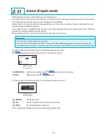
Page 25: ...to the Power 2 6 How to Use Control Panel 2 7 Setting Feeding Method 2 9 Pre Feed of Media Paper or Marking Film 2 9 Selecting Tool Condition 2 10 Running Cutting Tests 2 11 About Simple mode 2 11 1...

Page 26: ...ole Adjusting the Blade Length Blade length needs to be adjusted to perform optimal cut Perform few test cuts and set the optimal blade length CAUTION To avoid bodily injury handle cutter blades with...

Page 27: ...thick Maximum cutting distance of approximately 4000 m CB09UB K60 0 9mm PHP33 CB09N HS Dedicated blade for cutting color media film Suitable for cutting media up to 0 25 mm thick CB15U 1 5mm PHP33 CB...

Page 28: ...touching the tool immediately after the cutting plotter is turned on or whenever the tool is moving It is explained here using cutter plunger as an example CAUTION When pushing the tool holder with yo...

Page 29: ...Make sure that the tool bracket is engaged on the tool s flange and then tighten the screw Flange Bracket to hold tool Removing the tool When removing the tool turn it counterclockwise to remove the...

Page 30: ...n setting it in the media sensor Afterwards adjust the push roller so that it s lined up with the side of the media Loading Roll Media Operation 1 Lower the media set lever to raise the push rollers M...

Page 31: ...the media sensor Media sensors Slide the media stopper Media stopper Supplement The media must always be positioned over the media sensor See 2 4 Aligning the Push Rollers P 2 12 about the position of...

Page 32: ...east 2 meters Position the push rollers at least 5 mm inside the edges of the media Push roller Media 5 mm 5 mm 6 Pull the media taut to make sure that there is no slack in the conveyance path and the...

Page 33: ...lease be careful 8 When the set lever is up and the media is held down by the push rollers and the media stopper is unlocked pull out the roll media and give it slack Give it slack Create the same amo...

Page 34: ...lways be positioned over the media sensor For the location of media sensor see 1 2 Nomenclature See 2 4 Aligning the Push Rollers P 2 12 about the position of the push rollers 3 Position the media and...

Page 35: ...ake sure that there is no slack in the conveyance path and then raise the media set lever to lower the push rollers Set the sheet media so that the paper s edges line up with the guideline on the fron...

Page 36: ...CAUTION To move the push rollers the media set lever must be in the lowered position Supplement If a confirming push roller point message appears after setting the media and raising the media set lev...

Page 37: ...roller as a starting point and then set the push rollers so that they re on both sides of the media The Qe6000 can take media width of 55 mm or more Media sensor Media Grit roller Push roller CAUTION...

Page 38: ...g it on again otherwise problems may occur with the display 3 Turn on the Qe6000 by pressing the side of the switch LCD on the control panel is lit Supplement This screen is described as default scree...

Page 39: ...n ORIGIN It will set the current position as an origin point On the default screen pressing the ENTER and ORIGIN keys at the same time will allow you to reset the machine Only in Normal mode COPY Copy...

Page 40: ...ing Display of setting condition Only in Normal mode Command GP GL GP GL Command HP GL HP GL Command No Display Command Auto Select Step size 0 1 0 1 mm 0 05 0 05 mm 50 m 0 025 0 025 mm 25 m 0 01 0 01...

Page 41: ...COND TEST CONDITION screen Simple mode Menu screen Simple mode CONDITION screen Normal mode Menu screen Normal mode Page number is displayed in the upper right corner of the screen if there are too m...

Page 42: ...the position key screen When media is set the tool point can be moved P A 5 See the Menu Tree for list of the descriptions about each settings Normal mode In Normal mode 1 2 3 4 and keys can be used M...

Page 43: ...lear the CONDITION screen and return to default screen P 2 23 See 2 9 Selecting Tool Condition for the detailed tool condition Normal mode CONDITION screen 1 3 Normal mode Tool conditions are set in t...

Page 44: ...tect the media s edges 1 If you have already loaded the media the MEDIA TYPE menu appears Select the media type to suit the loaded media Check that the media stopper is unlocked and then select a medi...

Page 45: ...ished the tool carriage s location will become the initial point If the interface or command settings have not been made make these settings before sending the data If the settings have been made tool...

Page 46: ...Operation Supplement Perform the settings in Normal mode 1 Press the PAUSE MENU key in READY status MENU screen is displayed 2 Press the 4 key MEDIA MEDIA SETING screen 1 2 is displayed Supplement Pr...

Page 47: ...le mode Operation Supplement Use Normal mode for changing the type of blade offset and acceleration Pushing the 4 key RETURN allows you to return to the conditions screen without changing the settings...

Page 48: ...ayed Supplement It will return to CONDITION screen without changing the settings when you press the POSITION key CANCEL 2 Press the 1 key CONDITION No selection screen is displayed 3 Press the POSITIO...

Page 49: ...for outdoor use 0 05 to 0 08 CB09UB 10 to 14 30 or under 2 Film for decorative use 0 08 to 0 1 CB09UB 14 to 17 30 or under 2 Transparent or semitransparent film 0 08 to 0 1 CB09UB 14 to 20 30 or unde...

Page 50: ...eft on the backing sheet Specify a FORCE value that is as low as possible but that still leaves faint traces on the backing sheet Set the SPEED and ACCELERATION values as low as possible Weed the cut...

Page 51: ...s the POSITION key and select the setting Select the preset Media Type Tool Conditions 3 Press the 2 key SPEED to change the speed The screen below will appear Supplement Press the ENTER key SET confi...

Page 52: ...anging any settings The 0 value allows you to use the standard force setting If adjustment is necessary you can enter the adjusted value 6 Press the POSITION keys to change the current value The force...

Page 53: ...the 2 key TOOL TOOL setting screen is displayed 3 Press the 1 key CONDITION No selection screen is displayed Display may vary depending on the selected condition number 4 Press the POSITION keys to se...

Page 54: ...de type Setting range Setting value for other Ultra hard blade CB09UB 5 19 CB15U 5 29 CB15UB 5 7 CB09UB K60 5 19 Other 1 to 45 Set for the setting values not displayed in the cutter blade type when cu...

Page 55: ...ut changing the settings when you press the 4 key CANCEL 2 Press the 3 key SPEED SPEED setting screen is displayed Display may vary depending on the selected tool condition number 3 Press the POSITION...

Page 56: ...ngs when you press the 4 key CANCEL 2 Press the 4 key FORCE FORCE setting screen is displayed Display may vary depending on the selected condition number 3 Press the POSITION key and select the condit...

Page 57: ...en 2 3 without changing the settings when you press the 4 key CANCEL 3 Press the 1 key ACCELERATION ACCEL setting screen is displayed Display may vary depending on the selected tool condition number 4...

Page 58: ...r pen and make it touch the surface of the media Media Blade Supplement Blade length can be changed by spinning the adjustor on the blade Spinning it in the A direction pushes it out while spinning it...

Page 59: ...ress the COND TEST key in the default screen In Normal mode CONDITION screen 1 3 is displayed In Simple mode CONDITION screen 1 5 is displayed CONDITION screen Simple mode CONDITION screen Normal mode...

Page 60: ...cutting CAUTION When the 1 key FORCE is pressed the tool carriage will start moving so take care not to cut your fingers Supplement Test cut patterns can have their cut order and force changed as sho...

Page 61: ...P 2 32 and adjust the settings Peel off the triangle area and adjust so it cuts slightly into the backing sheet If the backing sheet has been cut through either the FORCE setting is too high or the cu...

Page 62: ...the location you wish to perform the blade length adjustment Supplement Perform the settings in Normal mode 3 Press the COND TEST key in the default screen CONDITION setting screen 1 3 is displayed 4...

Page 63: ...eturn to the TO ACHIEVE THE TARGET LENGTH screen Supplement T is the target value of the blade length and H is the current blade height amount Turning the blade length adjustment knob displays the num...

Page 64: ...40 14 Press the 3 key END Adjustment is completed and it will return to CONDITION screen 3 3 15 Press the COND TEST key I will be return to default screen After completing the settings press ENTER ke...

Page 65: ...mode RS 232C interface is not available In Simple mode ARMS settings cannot be used Even in Simple Mode performing operations commands for specifying the registration marks can be used For items with...

Page 66: ...ode When pressing the SIMPLE key the following screen appears The 1 key Yes allows you to change the mode after resetting the Qe6000 The 2 key No allows you to return to the previous screen without ch...

Page 67: ...to use for adequate time if the deviation of temperature and humidity is big Set the both push rollers at least 15mm inside the edge of media Set the sideway tension of the media uniform when setting...

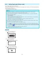
Page 68: ...inch 4 Press the POSITION keys to change the current setting Supplement Press the POSITION key to return to the MEDIA setting screen without changing any settings 5 Confirm the setting and press the...

Page 69: ...e Settings of Controls from Computer P 11 1 for more information Operation 1 Press PAUSE MENU key MENU screen is displayed 2 Press 2 key I F INTERFACE screen is displayed 3 Press 1 key HP GL ORIGIN PO...

Page 70: ...ress 2 key I F INTERFACE screen is displayed 3 Press 2 key GP GL STEP SIZE STEP SIZE setting screen is displayed 4 Press 1 key 0 100 mm 2 key 0 050 mm 3 key 0 025 mm or 4 key 0 010 mm Supplement Press...

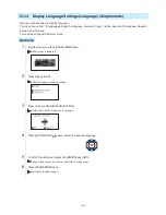
Page 71: ...n Normal mode Operation 1 In default screen press PAUSE MENU key MENU screen is displayed 2 Press 3 key ADV ADVANCE setting screen is displayed 3 Press 1 key LANGUAGE SELECTION LANGUAGE SELECTION scre...

Page 72: ...default screen press PAUSE MENU key MENU screen is displayed 2 Press 3 key ADV ADVANCE setting screen is displayed 3 Press 2 key LENGTH UNIT LENGTH UNIT setting screen is displayed 4 Press 1 key METR...

Page 73: ...is to start from the READY status media is set as a general condition Perform the operation described in this chapter after making the plotter in READY status referring to previous chapter PRODUCT SUM...

Page 74: ...ngs in Normal mode 1 Press the PAUSE MENU key MENU screen is displayed 2 Press the 1 key TOOL TOOL SETTING 1 3 screen is displayed 3 Tool is raised or lowered every time the 1 key TOOL UP DOWN is pres...

Page 75: ...POSITION keys once to move in the desired direction Tool carriage or the media will move toward the direction of the pressed POSITION key for 1 step Continuously Move Manually It can manually move co...

Page 76: ...2 is displayed 3 Press the 1 key MOVE STEP MOVE STEP screen is displayed Supplement Value chosen here will be the movement distance for the step movement 4 Press the 1 key 1 0mm or the 2 key 0 1mm Su...

Page 77: ...g area machine origin point Standby position of the pen carriage When using Sheet Media Seen from above To the top of the maximum cutting area Bottom of the operation area machine origin point Operati...

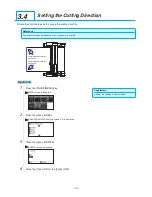
Page 78: ...turned on 2 Press the 1 key No 1 the 2 key No 2 the 3 key No 3 the 4 key No 4 the key No 5 the key No 6 the key No 7 or the key No 8 while simultaneously pressing the ENTER key Setting will be set an...

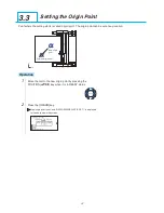
Page 79: ...tion New origin point Original origin point Operation 1 Move the tool to the new origin point by pressing the POSITION key when it is in READY status 2 Press the ORIGIN key New origin point is set and...

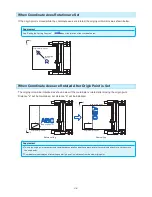
Page 80: ...t The origin point will be initialized as shown below if the coordinate is rotated after moving the origin point Distance a will be maintained but distance b will be initialized New origin point Origi...

Page 81: ...OSITION key I F in Normal mode or press the 2 key I F in Simple mode INTERFACE screen is displayed INTERFACE screen Simple mode INTERFACE screen Normal mode 3 Press the 2 key HP GL ORIGIN POINT in Nor...

Page 82: ...ation settings on Coordinate axes rotation settings off Operation Supplement Perform the settings in Normal mode 1 Press the PAUSE MENU key MENU screen is displayed 2 Press the 3 key AREA AREA PARAMET...

Page 83: ...e settings when you press the POSITION key CANCEL 5 Confirm the setting and press the ENTER key SET Setting will be set and it will return to AREA PARAMETERS screen 1 2 6 Press the PAUSE MENU key The...

Page 84: ...E MENU key Cutting will stop and following screen is displayed Supplement There is no effect on the selection of media type when the media set lever is moved up and down while pausing the cutting It i...

Page 85: ...en without clearing buffer memory when 2 key CANCEL is pressed In the case that the operation is interrupted and the buffer is cleared make sure that the data transfer is stopped If the data transfer...

Page 86: ......

Page 87: ...4 1 Chapter 4 Convenient Functions This chapter describes about the convenient functions of the plotter PRODUCT SUMMARY 4 1 Settings for Cutting 4 2 Copy Duplicate Cutting 4 3 Panel Cutting...

Page 88: ...t is possible to set the origin point at the center when the HP GL is selected Move the origin point to change the cutting position Upper right set position Image already cut Origin point It will only...

Page 89: ...the X and Y cut range for the areas on the upper right and lower left points to at least 10 mm An error message will appear for areas that are too small You will need to reset the settings for the up...

Page 90: ...is condition Supplement If the value is set to positive it is able to cut over where the push rollers are but the push rollers passes where it is cut creating a chance of bad feeding depending on the...

Page 91: ...eration below 2 In Simple mode there is no need to set anything so it is not available Perform pre feed for the amount to be used before cutting Leave the media in environment to use for adequate time...

Page 92: ...ayed Supplement Digits of settings can be changed by pressing the FAST key Setting range is from 20 0 to 5000 0 cm 7 874 to 1968 504 inch 4 Press the POSITION key and increase or decrease the setting...

Page 93: ...saved even if the power is shut off MIRROR mode off MIRROR mode on Operation Supplement Perform the settings in Normal mode 1 Press the PAUSE MENU key MENU screen is displayed 2 Press the 3 key AREA...

Page 94: ...e shrink scale Scale It can enlarge or shrink cutting The rate of enlargement or shrinkage of the cutting data can be changed by settings Reference This setting will be saved even if the power is shut...

Page 95: ...n 1 2 without changing the settings when you press the POSITION key CANCEL 5 Confirm the setting and press the ENTER key SET Setting will be set and it will return to AREA PARAMETERS setting screen 1...

Page 96: ...sort when you need to copy cutting with large data See Sorting the Cutting Data P 8 2 for data sort Watch out that it does not fall out of media when cutting with copy function If the original cutting...

Page 97: ...en setting the copy interval set MEDIA CHANGE MODE to OFF NO DATA FOR COPY IN BUFFER is displayed if there is no data in the buffer memory Send the cutting data If too much data is sent from the buffe...

Page 98: ...urn to COPY mode screen Supplement Copy interval can be set when MEDIA CHANGE MODE is turned off Copy space can be set from 1 0 to 10 0 mm 0 039 to 0 39 inch This setting is maintained even if the pow...

Page 99: ...media selection will be chosen from what was selected before copying If there is no data in the buffer memory There is no data for copying in the buffer will be displayed Please send cutting data If t...

Page 100: ...Supplement Cutting data is stored even if the media is exchanged It can be copied as many times until the buffer memory is cleared It can be copied again after exchanging the media by pressing COPY ke...

Page 101: ...is caused by a command even if multiple pieces of data are sent in before the cutting finishes even when numerous pieces of partition pastern data are in the plotter buffer When partition pastern and...

Page 102: ...the setting digits The partition length can be set from 1 0 to 2000 0 cm 0 394 to 787 402 inch 7 Press the 2 key DIVIDE LENGHT DIVIDE LENGHT setting screen is displayed 8 Press the POSITION key and i...

Page 103: ...media using ARMS to adjust for printing position discrepancies high precision cutting can be done It is possible to perform a multiple registration mark adjustment or segment area adjustment by linki...

Page 104: ...it may not scan the registration mark correctly if it is turned off When partition pastern is on the ARMS function cannot be used In Simple mode ARMS settings cannot be made Even in Simple mode perfo...

Page 105: ...the application software cannot be used Create the registration mark in accordance with following conditions Thickness of the line is between 0 3 to 1 0 mm Size of the registration mark is between 4 t...

Page 106: ...canning area Adjust the MARK DISTANCE so it can scan the registration mark correctly See Setting Mark Distance P 5 14 Clean any dirt or foreign objects from the media Any dirt or foreign object might...

Page 107: ...and set that sheet media on the cutting plotter Send the cutting data from the computer to cutting plotter Also scan the registration mark on the sheet media with the cutting plotter determine the ori...

Page 108: ...lack on white background It makes harder to scan the registration mark on colored background or written in colors other than black Adjust the sensitivity level of the sensor See Adjusting the Sensor L...

Page 109: ...e Registration Mark Scan Position Supplement Turning the Paper Weight setting off can result in the Registration Mark not being read correctly For information about the Paper Weight setting please ref...

Page 110: ...detect and the area that can be cut becomes smaller 1 axis adjustment 2POINT detection Supplement The printable range on the chart to the left is for when the registration mark detection movement dist...

Page 111: ...4 axes adjustment 4POINT detection Supplement Distance between the registration marks can be adjusted The printable range on the chart to the left is for when the registration mark detection movement...

Page 112: ...e 2 key NUMBER OF POINTS NUMBER OF POINTS setting screen is displayed Supplement It will return to MARK SCAN MODE setting screen without changing the settings when you press the POSITION key PREVIOUS...

Page 113: ...splayed 3 Press the POSITION key ARMS SETTING screen 2 4 is displayed Supplement It will return to ARMS SETTING screen 2 4 without changing the settings when you press the POSITION key CANCEL 4 Press...

Page 114: ...marks with larger sizes However if the registration mark is large then the cutting area will become tighter Feed direction of media Feed direction of media When detecting a registration mark it will s...

Page 115: ...E MARK SIZE setting screen is displayed 5 Press the POSITION key and increase or decrease the setting value Supplement It will return to ARMS SETTING screen 2 4 without changing the settings when you...

Page 116: ...distance for MARK DISTANCE Y Feed direction of media Set this distance for MARK DISTANCE Y Set this distance for MARK DISTANCE X Set this distance for MARK DISTANCE X Detection is started from the pos...

Page 117: ...een is displayed Supplement Digits of settings can be changed by pressing the FAST key Setting range is from 0 0 mm to 50000 0 mm 0 0 to 1968 504 inch 8 Press the POSITION key and increase or decrease...

Page 118: ...the CUSTOM UNIT to 5 mm and if the distance between the scanned registration marks were 312 mm it will be rounded off to the closest 5 mm and the adjustment will be performed so the ideal distance wi...

Page 119: ...d it will return to DISTANCE ADJUST screen 7 The procedures are different depending on the selected mode When USER or STANDARD modes are selected Jump to step 9 When CUSTOM mode is selected Press the...

Page 120: ...tting Point X offset Y offset Registration mark point 1 Origin point after registration mark is read Operation Supplement Perform the settings in Normal mode 1 Press the PAUSE MENU key MENU screen is...

Page 121: ...played Supplement Digits of settings can be changed by pressing the FAST key Setting range is from 1000 0 to 1 000 0 mm 39 37 to 39 37 inch 9 Press the POSITION key and increase or decrease the settin...

Page 122: ...attached CD Registration Mark File format File name MARK TYPE 1 pdf ARMStest_type1 pdf eps ARMStest_type1 eps MARK TYPE 2 pdf ARMStest_type2 pdf eps ARMStest_type2 eps For level adjustment pattern pl...

Page 123: ...ion of media Align the tool to this area Registration mark scan area Supplement It will return to ARMS SETTING screen 3 4 without changing the settings when you press the 4 key CANCEL It may not scan...

Page 124: ...s the 2 key ARMS ARMS SETTING screen 1 4 is displayed 3 Press the POSITION key ARMS SETTING screen 4 4 is displayed Supplement It will return to ARMS setting screen 4 4 without changing the settings w...

Page 125: ...displayed 6 Press the POSITION key and increase or decrease the setting value 7 Confirm the setting and press the POSITION key PREVIOUS SENSING LEVEL is selected and it will return to SENSING LEVEL sc...

Page 126: ...rint the Test Pattern 1 to test MARK TYPE 1 and Test Pattern 2 to test MARK TYPE 2 Standard registration mark is inside the ARMS Test Files folder of the accessory CD Registration Mark File Format Fil...

Page 127: ...g the POSITION key Registration mark scan area Feed direction of media MARK TYPE 1 MARK TYPE 2 Feed direction of media Move the tool inside this area Move the tool inside this area Supplement Followin...

Page 128: ...ion marks cannot be scanned or the difference is too big Operation 1 Press the PAUSE MENU key MENU screen is displayed 2 Press the 2 key ARMS ARMS SETTING screen 1 4 is displayed 3 Press the POSITION...

Page 129: ...estriction on the shape style of the registration marks that can be scanned See Shape Pattern of Registration Mark P 5 2 Adjust After Plotting the Adjustment Registration Mark This section describes t...

Page 130: ...he 1 key TEST PATTERN Following message is displayed 8 Press the POSITION key and move the tool carriage to the position to plot the registration mark position nothing is printed Supplement It will re...

Page 131: ...sing the registration mark plotted in step 9 measure the distance of how much the comparison registration mark needs to be moved so both will overlap and record the value As an example in the figure a...

Page 132: ...y It will return to the default screen Detect the Registration Mark for Adjustment on the Media and Enter the Value Method to enter the adjustment value which is the difference between the scanned reg...

Page 133: ...nning of the registration mark Feed direction of media Align the tool to this area Registration mark scan area Supplement It will return to ARMS SETTING screen 3 4 without plotting when you press the...

Page 134: ...isplayed Supplement Setting range is from 3 0 to 3 0 mm 0 118 to 0 118 inch 11 Press the POSITION key and increase or decrease the setting value Set the X value measured in step 9 12 Confirm the setti...

Page 135: ...point Point 1 by pressing the ENTER key without moving to the detect start position of tool the registration mark position will be automatically retrieved The Please move the tool and press ENTER mes...

Page 136: ...ff 6 Confirm the setting and press the ENTER key SET Setting will be set and it will return to ARMS SETTING screen 3 4 Supplement It will return to EGISTRATION MARK setting screen 3 4 without changing...

Page 137: ...n The media might lift and it may not scan the registration mark correctly if it is turned off Adjust with 2POINTS 2POINTS adjustment will scan 2 registration marks aligned in the media transportation...

Page 138: ...Pattern of Registration Mark P 5 12 Setting Registration Mark Size P 5 14 Setting Mark Distance P 5 16 Setting Distance Adjustment Between the Registration Mark P 5 18 Setting Offset Between the Regis...

Page 139: ...registration mark position Difference in X Operation Supplement See Loading Media Paper or Marking Film P 2 6 for loading the media 1 Load the media with registration marks 3POINTS plotted 2 Set the...

Page 140: ...Adjust Automatically P 5 41 Adjust Manually Adjust with 4POINTS 4POINTS adjustment will scan 4 registration marks in the corners where the adjustment is done measuring the tilting of the X and Y axes...

Page 141: ...Pattern of Registration Mark P 5 12 Setting Registration Mark Size P 5 14 Setting Mark Distance P 5 16 Setting Distance Adjustment Between the Registration Mark P 5 18 Setting Offset Between the Regis...

Page 142: ...Left figure is for 4POINTS Size and position of the registration scan start area is same for 2POINTS or 3POINTS Registration mark scan area Feed direction of media MARK TYPE 1 MARK TYPE 2 Feed direct...

Page 143: ...CANCEL Distance input screen for point 3 is displayed if it is set to 3POINTS or more so repeat steps 4 and 5 to set 5 Confirm the setting and press the ENTER key SET Adjustment by scanning the regis...

Page 144: ...to ARMS SETTING screen 1 4 without scanning when you press the POSITION key CANCEL 3 Confirm the position of the tool and if it is OK press the ENTER key Registration marks are scanned Following mess...

Page 145: ...e the registration mark is scanned Supplement Measured distance is displayed in the top line in the DISTANCE input screen Input value initially same as measured value is displayed under that If the in...

Page 146: ......

Page 147: ...ain how to match up points while manually confirming the media and tool cutter pen or plotting pen points The ARMS function cannot be used for accurately matching up points PRODUCT SUMMARY 6 1 Outline...

Page 148: ...r registration marks necessary to get XY axes and origin point Setting of Mark Scan Mode and Number of Adjustment Marks To perform the AXIS ALIGNMENT set the MARK SCAN MODE to AXIS ALIGNMENT Select th...

Page 149: ...so as to make the inclination small please perform adjustment operations Axis adjustment will be cleared when point 1 and point 2 is set to same point Operation Supplement Confirm that the push roller...

Page 150: ...en you press the POSITION key CANCEL 9 Press the 1 key 2POINTS the 2 key 3POINTS or the 3 key 4POINTS This will select the number of registration marks and return you to the MARK SCAN MODE setting scr...

Page 151: ...ng the FAST key 14 Press the POSITION key to set the original distance on the data Supplement It will return to default screen without changing the settings when you press the POSITION key PREVIOUS DI...

Page 152: ......

Page 153: ...blades when the actual cutting is done Adjust the moving speed and force of the tool and the control method to prevent these problems This chapter describes the setting regarding the quality of the cu...

Page 154: ...to precisely cut corners where two straight lines meet See below With the tangential emulation the blade is advanced so it will overcut at the corners before raising the tool Then it will be lowered...

Page 155: ...layed 3 Press the 2 key TANGENT EMULATION TANGENT EMULATION setting screen is displayed 4 Press the POSITION keys and select the tool condition number CONDITION No 5 Press the 1 key MODE1 the 2 key MO...

Page 156: ...1 3 is displayed 2 Press the POSITION key CONDITION setting screen 2 3 is displayed 3 Press the 3 key OVERCUT OVERCUT setting screen is displayed 4 Press the 1 key Condition No CONDITION No selection...

Page 157: ...nt Setting range is from 0 0 to 0 9 mm 0 0 to 0 035 inch 11 Press the POSITION key and increase or decrease the setting value 12 Confirm the setting value and press the POSITION key PREVIOUS Length fo...

Page 158: ...is 25 and the initial down force is 4 for example the cutting force applied immediately after the pen is lowered will be 29 The upper limit for added value is 31 Operation Supplement Perform the setti...

Page 159: ...be what you intended if the set value is too large It is recommended to set to 1 for normal use Operation Supplement Perform the settings in Normal mode 1 Press the PAUSE MENU key MENU screen is displ...

Page 160: ...the reference angle in good balance Supplement This setting is maintained even if the power is turned off Operation Supplement Perform the settings in Normal mode 1 Press the PAUSE MENU key MENU scre...

Page 161: ...can be specified for each CONDITION No Supplement This setting will be saved even if the power is shut off Operation Supplement Perform the settings in Normal mode 1 Press the COND TEST key CONDITION...

Page 162: ...s displayed Supplement Setting range for adjustment value is 2 00 to 2 00 Press the FAST key to change the setting digits 10 Press the POSITION key and increase or decrease the Y DISTANCE ADJUST value...

Page 163: ...ange will but the Initial Blade Control Position out of the range of the cutting area Feed direction of media Feed direction of media 2mm Push roller Initial Blade Control Position Setting Point Set a...

Page 164: ...key 2mm BELOW 0 08 inch BELOW Supplement It will return to TOOLS setting screen 2 3 without changing the settings when you press the POSITION key CANCEL 6 Confirm the setting and press the ENTER key...

Page 165: ...mode 1 Press the PAUSE MENU key TOOL setting screen 1 3 is displayed 2 Press the 1 key TOOL TOOLS SETTING screen 1 3 is displayed 3 Press the 3 key OFFSET FORCE OFFSET FORCE setting screen is display...

Page 166: ...t is located under the tool carriage It cannot be seen from outside Operation 1 Press the PAUSE MENU key MENU screen is displayed 2 Press the 2 key ARMS ARMS SETTING screen 1 4 is displayed 3 Press th...

Page 167: ...o ARMS setting screen 3 4 without changing the settings when you press the POSITION key CANCEL 6 Confirm the setting and press the ENTER key SET Setting will be set and it will return to ARMS SETTING...

Page 168: ......

Page 169: ...ics of the media and tools and the contents of the cutting data This chapter describes the settings affecting the cutting time In addition to this chapter there are setting affecting the cutting times...

Page 170: ...ored in the buffer memory so it takes time to start the cutting Sorting might not be effective for the data that is created efficiently Process may be faster to turn off the sorting on the plotter if...

Page 171: ...SITION key CANCEL 6 Confirm the setting and press the ENTER key SET Setting will be set and it will return to TOOLS SETTING screen 2 3 Supplement mark is displayed at the right of the screen when SORT...

Page 172: ...maintained even if the power is turned off Setting of the AUTO PRE FEED length is not linked to the setting of the page length Change the setting for the page length if the cutting area is to be long...

Page 173: ...the setting digits 7 Press the POSITION key and increase or decrease the setting value 8 Confirm the setting value and press the POSITION key CANCEL FEED LENGTH is selected and return to AUTO PRE FEE...

Page 174: ...ion Supplement Perform the settings in Normal mode 1 Press the PAUSE MENU key MENU screen is displayed 2 Press the 4 key MEDIA MEDIA SETTING screen 1 2 is displayed 3 Press the 4 key INITIAL FEED INIT...

Page 175: ...Perform Automatic Pre Feed When Media is Set Initial Feed P 8 4 Perform Automatic Pre Feed When Cut Data is Received Supplement This setting will be saved even if the power is shut off Operation Supp...

Page 176: ...to MEDIA SETTING screen 2 2 without changing the settings when you press the POSITION key CANCEL 6 Confirm the setting and press the ENTER key SET Setting will be set and it will return to MEDIA SETTI...

Page 177: ...t off Operation Supplement Perform the settings in Normal mode 1 Press the PAUSE MENU key MENU screen is displayed 2 Press the 1 key TOOL TOOLS SETTING screen 1 3 is displayed 3 Press the POSITION key...

Page 178: ...en 2 3 without changing the settings when you press the POSITION key CANCEL 6 Confirm the setting and press the ENTER key SET Setting will be set and it will return to TOOLS SETTING screen 2 3 7 Press...

Page 179: ...sly it will directly move to the last coordinate received Cutting time can be reduced if it is set to DISABLED if the time to move the tool in raised status is wasteful Supplement This setting will be...

Page 180: ...en 3 3 without changing the settings when you press the POSITION key CANCEL 6 Confirm the setting and press the ENTER key SET Setting will be set and it will return to TOOLS SETTING screen 3 3 7 Press...

Page 181: ...9 1 Chapter 9 Setting Regarding Interface This chapter describes setting regarding interface PRODUCT SUMMARY 9 1 Setting Interface...

Page 182: ...sconnect the USB cable within a 5 second period of connecting it Do not disconnect the cable during data transfer Do not connect multiple plotters to a single computer using the USB interface RS 232C...

Page 183: ...ement Perform the settings in Normal mode 1 Press the PAUSE MENU key in the default screen MENU screen is displayed 2 Press the POSITION key I F in Normal mode INTERFACE SETTING screen 1 2 is displaye...

Page 184: ...and Storing RS 232C Settings Operation Supplement Perform the settings in Normal mode 1 Press the PAUSE MENU key in the default screen MENU screen is displayed 2 Press the POSITION key I F in Normal...

Page 185: ...reen is displayed Supplement Match the setting value of the application to be used It will return to RS 232C setting screen without changing the settings when you press POSITION key CANCEL 9 Press the...

Page 186: ...Ack setting is valid only when it is set to HP GL It will be set to HARDWIRE even if Enq Ack is selected when it is set to GP GL 13 Press the 1 key HARDWIRE the 2 key Xon off or the 3 key Enq Ack HAND...

Page 187: ...10 1 Chapter 10 Settings Regarding Operation Environment This chapter describes setting regarding the operation environment...

Page 188: ...or press the 3 key ADV in Simple mode ADVANCE setting screen is displayed ADVANCE setting screen Simple mode ADVANCE setting screen Normal mode 3 Press the 2 key LANGUAGE SELECTION in Normal mode or...

Page 189: ...y ADV in Normal mode or press the 3 key ADV in Simple mode ADVANCE setting screen is displayed ADVANCE setting screen Simple mode ADVANCE setting screen Normal mode 3 Press the 3 key LENGTH UNIT in No...

Page 190: ...ged Please be sure to configure the area Operation Supplement Perform the settings in Normal mode 1 Press the PAUSE MENU key in the default screen MENU screen is displayed 2 Press the POSITION key ADV...

Page 191: ...SH ROLLER SENSOR PUSH ROLLER SENSOR setting screen is displayed Supplement If DISABLED is selected push roller detection is not performed It will not generate error even if the inner push rollers are...

Page 192: ...USE MENU key in the default screen MENU screen is displayed 2 Press the POSITION key ADV ADVANCE setting screen 1 2 is displayed 3 Press the POSITION key ADVANCE setting screen 2 2 is displayed 4 Pres...

Page 193: ...fault screen MENU screen is displayed 2 Press the POSITION key ADV ADVANCE setting screen 1 2 is displayed 3 Press the POSITION key ADVANCE setting screen 2 2 is displayed 4 Press the 3 key BEEP FOR K...

Page 194: ......

Page 195: ...11 1 Chapter 11 Settings of Controls from Computer This chapter describes setting regarding the controls from the computer...

Page 196: ...nds after completing the cutting Send next data after 10 seconds has past after previous cutting when sending data with different command Operation Supplement Perform the settings in Normal mode In si...

Page 197: ...e when PROGRAM is selected The values set from the control panel is maintained and the values set from the software is erased when the power is turned off Operation Supplement Perform the settings in...

Page 198: ...TERFACE setting screen is displayed INTERFACE screen Simple mode INTERFACE screen Normal mode 3 Press the 4 key GP GL STEP SIZE in Normal mode or press the 2 key GP GL STEP SIZE in Simple mode LANGUAG...

Page 199: ...NU key in the default screen MENU screen is displayed 2 Press the POSITION key I F INTERFACE setting screen 1 2 is displayed 3 Press the POSITION key INTERFACE setting screen 2 2 is displayed 4 Press...

Page 200: ...n in the lowered status when it is set to TOOL DOWN Supplement This only has an effect on the cutter tool Operation Supplement Perform the settings in Normal mode 1 Press the PAUSE MENU key in the def...

Page 201: ...erform the settings in Normal mode 1 Press the PAUSE MENU key in the default screen MENU screen is displayed 2 Press the POSITION key I F INTERFACE setting screen 1 2 is displayed 3 Press the 3 key HP...

Page 202: ...MENU key in the default screen MENU screen is displayed 2 Press the POSITION key I F INTERFACE setting screen 1 2 is displayed 3 Press the POSITION key INTERFACE setting screen 2 2 is displayed 4 Pres...

Page 203: ...Chapter 12 Maintenance This chapter describes the settings for the maintenance PRODUCT SUMMARY 12 1 Daily Maintenance 12 2 Replacing Cutter Blade 12 3 Cleaning the Cutter Pen 12 4 Cutter Plunger Exch...

Page 204: ...otter s paper sensors using a cloth moistened in a neutral detergent diluted with water Never use thinner benzene alcohol or similar solvents to clean the sensors cleaners such as these will damage th...

Page 205: ...ob in the direction of the B arrow and pull the blade into the plunger One scale unit approximately 0 1 mm Graduation Graduation 2 Turn the plunger cap in the counter clockwise direction to remove it...

Page 206: ...move build up CAUTION To avoid bodily injury handle cutter blades with care Cleaning 1 Please clean off paper dust and media build up from the blade After cleaning it return it to its proper place Spi...

Page 207: ...down due to friction with the media When the tip of the cutter plunger gets worn down cut quality suffers When the tip of the plunger cap gets worn down it is recommended that you exchange the cutter...

Page 208: ......

Page 209: ...s wrong or it does not work right It also describes the settings of the plotter confirming the cutting data and method to create test patterns PRODUCT SUMMARY 13 1 Troubleshooting 13 2 Printing the Se...

Page 210: ...e inlet and the electrical outlet Check that the power is supplied to the electrical outlet Contact your nearest Signwarehouse dealer if the problem still exists Nothing is displayed on the LCD panel...

Page 211: ...disturbing the operation and turn on the plotter after turning it off once External force is applied to the pen carriage while cutting Move the object disturbing the operation and turn on the plotter...

Page 212: ...l up speed Perform feeding P2 25 Setting the Tool Condition P2 22 Pre Feed of Media Paper or Marking Film P8 9 Setting the Tool Up Speed Distance adjust value is not correct Perform distance adjust P7...

Page 213: ...ia cannot be pulled up using retack sheet The retack sheet is not sticky enough Switch to a stickier retack sheet Media gets entangled during cutting Reduce the blade length Lower the FORCE setting Cl...

Page 214: ...figure to drive the plotter from the menu of the software The software configuration regarding the output device has been changed Reset the interface settings of the software The plotter s interface c...

Page 215: ...ommand with the correct number of parameters E03003 Error 3 An unusable parameter was executed Execute a recognizable parameter E03005 Error 5 An unusable character set was specified Specify usable ch...

Page 216: ...many parameters in the I O related command Check the program E03015 Error 15 Framing error parity error or overrun error has occurred Set the RS 232C transmission condition E03016 Error 16 Interface...

Page 217: ...ithin the plotting area for sensor position adjustment Move the media toward center and plot the test pattern E04008 Media end was detected while detecting the registration mark Check the media Check...

Page 218: ...E04018 Media set lever was lowered Reload the media and try again E04019 There was cancel operation by the user Redo the process E04020 There is a defect in the detection settings value Check the set...

Page 219: ...er E01010 The plotter is defective Contact your sales representative or nearest Signwarehouse dealer E01011 The plotter is defective Contact your sales representative or nearest Signwarehouse dealer E...

Page 220: ...power back on If the error display continues to show please contact the store where you bought the product or our Customer Center E05001 Data larger than the buffer size cannot be copied Perform norm...

Page 221: ...13 13 Caution Message Symptom LCD Display Description W06001 When command is set to auto the DUMP mode is not available W06002 When panel cutting is on copy and origin point settings cannot be changed...

Page 222: ...upplement See Attaching a Tool P 2 4 for setting the pen tool For changing the tool conditions please refer to Selecting Tool Condition P 2 23 and for tool settings please refer to Setting the Tool Co...

Page 223: ...carriage will start moving so there is a chance of injury 8 Confirm that movable parts of the tool and media can safely operate and press the ENTER key Selected page of the CONDITION LIST is printed...

Page 224: ...and the command If the command setting is Auto the dump list of the cutting data is not output Please set the command to GP GL or HP GL Operation Supplement See Loading Media Paper or Marking Film P 2...

Page 225: ...ere is a chance of injury 7 Confirm that operation area of tool and media is safe Supplement It will return to TEST menu screen without printing by pressing the 2 key CANCEL DATA DUMP 8 Press the 1 ke...

Page 226: ...on such as loading media is performed Operation 1 Confirm that the power is turned off 2 Turn the power on without loading the media Supplement Perform the settings in Normal mode 3 Press the PAUSE ME...

Page 227: ...Y motor signal 8 Tool height signal 9 1 key 10 2 key 11 3 key 12 4 key 13 POSITION key 14 POSITION key 15 POSITION key 16 POSITION key 17 ENTER key 18 COND TEST key 19 ORIGIN key 20 FAST key 21 SIMPL...

Page 228: ...occurred and right column is the type of the error 4 error messages are displayed at once If there are more error messages next 4 messages will be displayed by pressing the POSITION key 5 Press the 1...

Page 229: ...A 1 Appendix This chapter describes the specification of the plotter PRODUCT SUMMARY A 1 Main Specifications A 2 Options and Supplies A 3 External Dimensions A 4 Menu Tree A 5 Initial Setting...

Page 230: ...ed fiber tip and oil based ballpoint Compatible media Mono vinyl chloride media fluorescent media and reflective media up to 0 25 mm thick Excluding high intensity reflective film Interface RS 232C US...

Page 231: ...set of 5 CB15U 5 1 5 mm diameter supersteel blade set of 5 CB15UB 2 1 5 mm diameter supersteel blade for cutting small text set of 2 CB09UB K60 5 0 9 mm diameter supersteel blade set of 5 Water based...

Page 232: ...A 4 Qe6000 900 1046 593 Unit mm Dimensional accuracy 5mm A 3 External Dimensions...

Page 233: ...A 5 Simple Menu CUT TESTS CUT TESTS CONDITION setting 1 3 COND TEST MENU screen PAUSE MENU MEDIA SETTING 1 1 1 COPY INTERFACE setting 1 1 2 ADVANCE setting 1 1 3 Default screen A 4 Menu Tree...

Page 234: ...A 6 Normal Menu CONDITION setting 1 3 CONDITION setting 2 3 CONDITION setting 3 3 COND TEST ENTER COPY 3 Continued Default screen...

Page 235: ...A 7 MENU screen TOOLS SETTING 1 3 TOOLS SETTING 2 3 TOOLS SETTING 3 3 ARMS SETTING 1 4 PAUSE MENU MENU screen PAUSE MENU 1 2 Continued ARMS SETTING 2 4 Default screen Continued...

Page 236: ...A 8 PAUSE MENU 3 Default screen Continued ARMS SETTING 1 4 Continued ARMS PARAMETERS 2 2 ARMS SETTING 2 4 ARMS SETTING 3 4 ARMS SETTING 4 4 MENU screen AREA PARAMETERS 1 2...

Page 237: ...PAUSE MENU 4 Default screen Continued ARMS PARAMETERS 1 2 MENU screen PAUSE MENU MENU screen MEDIA SETTING 1 2 MEDIA SETTING 2 2 INTERFACE SETTING 1 2 INTERFACE SETTING 2 2 AREA PARAMETERS 2 2 Contin...

Page 238: ...A 10 PAUSE MENU PAUSE MENU Default screen Continued MENU screen TEST 1 2 MENU screen ADVANCE setting 2 2 ADVANCE setting 1 2 Default screen Finish...

Page 239: ...Y MANUAL INITIAL BLADE CONTROL POSITION 2 mm BELOW 0 08 inch BELOW TOOL UP MOVE DISABLED ARMS SETTING MARK SCAN MODE OFF NUMBER OF POINTS 4 POINTS MARK DISTANCE X X 0 0 mm MARK DISTANCE Y Y 0 0 mm MAR...

Page 240: ...ON to INITIAL DOWN FORCE Same as Condition No 1 CONDITION NO 3 TOOL CONDITION NO CONDITION NO 3 TOOL CB09U SPEED FORCE ACCELERATION 30 12 2 Same as Condition No 1 from TANGENTIAL EMULATION to INITIAL...

Page 241: ...the Cutting Condition Condition No 3 6 Circle Command Resolution 11 8 CIRCLE RESOLUTION 11 8 Cleaning the Cutter Pen 12 4 COMMAND 11 2 Command 11 2 COMMAND 11 5 COMMAND W 11 6 COND TEST key 2 15 2 19...

Page 242: ...Distance 5 14 Mark Scan Mode and Number of Adjustment Marks 6 2 MARK SCAN Mode and Numbers 5 7 MARK TYPE 5 2 MEDIA 2 18 Media 2 6 Media Change mode is off 4 10 Media Change mode is on 4 13 Media Cutte...

Page 243: ...nnector 1 3 S Safety Precautions ii Scale 4 8 Scan Range Necessary to Detect the Registration Mark 5 3 Screen LCD 2 16 Self Diagnostic Test 13 18 Sensor 10 4 Sensor Level 5 20 5 22 Set the enlarge shr...

Page 244: ......

Page 245: ...Specifications are subject to change without notice Qe6000 User s Manual VEXQe60 UM 151 December 10 2012 1st edition 01 SIGN Warehouse com...

Page 246: ......

Reviews: