


.
Slide on the R/C Solder Link. Press the tip of the soldering iron firmly to the outside of the barrel of the R/C Solder Link. Let
it heat! Keep the iron against the barrel while you touch the tip of your solder to the joint (not to the soldering iron). When
the two parts get hot enough, the solder will melt and flow into the joint. Continue flowing solder into the joint until it is full.
Let cool. Wipe the solder joint clean with a rag.
Landing Gear
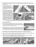
130.
Bolt the aluminum Main Landing Gear in place on the fuselage with two 4-40 x
1/2" bolts.
131.
Assemble the wheels to the main landing gear as shown in this drawing. First slide
the 3" dia. wheel (not provided) onto a 6-32 x 1-1/2" Mounting Bolt. Thread on two
6-32 hex nuts, side by side. Run both hex nuts up close to the wheel hub, but not
too close - make sure that the wheel can still turn freely on the axle. Tighten the
hex nuts up against each other. Stick the end of the bolt thru the aluminum gear
leg and thread on 6-32 aircraft locking nut. Tighten securely.
132.
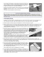
Because of the tiny size of the tailwheel wire, we prefer to use soldered washers to mount the tailwheel instead of wheel
collars. First solder a #2 flat metal washer at the inner bend of the tailwheel wire as shown. Helpful Hint: Slide a small piece
of small diameter silicone fuel line tubing onto the axle wire to hold the washer in position while you solder. After the solder
joint has cooled, remove the fuel tubing.
133.
Slip the tailwheel onto the axle, and then put a small piece of thin cardstock or paper (the paper serves two purposes - to
protect the wheel hub from the solder, and serves as a spacer to insure that the wheel will turn freely after the soldering).
Next slide a #2 flat metal washer on the wire and solder it place.
A Soldering Tip: The secret to easy soldering is cleanliness. Sand the washers and the wire where the washers are to be
soldered and then wipe everything clean with alcohol before attempting to solder.
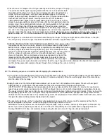
134.
Lay the Nylon Tailwheel Bracket in position on the bottom of the fuselage, aligning the rear hole in the bracket with the hole
in the fuselage. Drill three 1/16" dia. pilot holes in the bottom of the fuselage, and attach the Tailwheel Bracket using three
#2 x 3/8" Sheet Metal Screws.
Fuel Tank
The following instructions and photos pertain specifically to a 6 oz. Du-Bro Fuel Tank, although the proceedure for
assemblying other brands of plastic "clunk" tanks should be basically the same.
135.
Pull the stopper cap out of the front of the fuel tank. Inside the tank there should be two brass tubes, one brass clunk
weight, and a short piece of fuel line tubing. Shake the tank to get these parts out through the hole. You may have to reach
inside the tank with a tweezers or needle nose pliers to get a hold of the fuel line tubing and pull it out . (CAUTION: Don’t
squeeze too hard and put a hole in the tubing). Now shake the tank a few more times to make sure there is no dirt or plastic
shavings inside!
136.
Take a look at the stopper cap. Rotate the front plastic cap, the middle rubber stopper, and the rear plastic cap until the
holes line up. You should be able to see daylight through two of the three holes. NOTE: We will only be using two of the
holes. Leave the third hole closed.
137.
Cut one of the brass tubes to 1-1/2" long - this will be the Fuel Feed Tube. Cut the other brass tube to 2" long - this will be
the Vent Tube. A razor saw works well for cutting the brass tubing. Clean up the sawn end of the tubing with 220 grit
sandpaper to remove any burrs or sharp edges that might cut the fuel line tubing later.