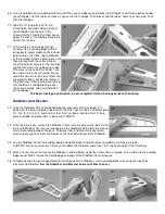
SIG KADET LT-25 Instruction Book Download Page 20

COVERING

 
In this step you need to cover all the parts of your model with the covering material of your choice, before proceeding on to 
Final Assembly of the model.


General Notes

 
There are many different covering materials available for finishing model airplanes. They range from raw coverings that 
must be bonded to the structure with adhesive and then painted; to iron-on plastic materials that have the color and finish 
built right in. 
 
The choice of which type of covering material to use on your KADET LT-25 is a matter of personal choice. However, if this 
is your first model airplane, we recommend that you chose one of the popular pre-finished iron-on plastic film coverings. 
This type of covering material provides a high gloss, durable finish that is easy to apply and repair. It goes on relatively 
quick and is not near as messy or smelly as using a covering material that must be painted. All of the KADET LT-25 
prototypes built here at the SIG factory were finished with SIG SUPERCOAT IRON-ON PLASTIC COVERING.  
 
Since all iron-on plastic covering materials come with detailed step-by-step instructions on how they should be applied, we 
will not go into a repetitive step-by-step sequence here. We will instead outline some ideas that are specific to the KADET 
LT-25. Be sure to read all the instructions that come with your covering material and follow them carefully. NOTE: There 
are also complete books and video tapes available on applying iron-on covering materials. These sources can be very 
helpful, providing a lot more tips than we can cover in these instructions. Often times, the video tapes can be rented or 
borrowed from your local hobby shop or model airplane club.


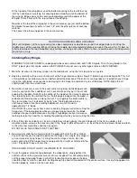
Choice Of Color Scheme

 
One of modeling’s pleasures is the chance to decorate your model to suit your own taste. There are a huge variety of 
after-market items available in the hobby shops to dress up your airplane. Striping tapes and trim sheets in every color of 
the rainbow, stick-on decals and markings, are all available and easy to apply.
 
You can go for a military look, a Cessna-like civil aviation look, or something totally wild in vivid neon colors. Your 
imagination is the only limit! 
 
If this is your first model, our advice is to keep the color scheme simple and visible. The most economical way to go is to 
choose one primary color for the entire model. Choose a light color! Covering the entire model in black, dark blue, gray, 
etc., is not a good choice. In the air a dark colored model will quickly turn into a black silhouette, and it will be difficult to 
distinguish which way the airplane is going. A light color is more visible at greater distances! White, yellow, orange, cream, 
and neon colors are excellent choices for a trainer model.
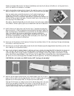
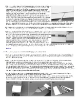
 

KIT COLOR SCHEME

The LT-25 kit includes one sheet of stick-on decals to duplicate the windows on the fuselage 
and fin. On our kit box model, we covered the back part of the wing with white covering 
material, and then covered the front part of the wing with blue covering. The blue covering 
overlaps approximetely 3/8" onto the white covering material, at the main spar. The fuselage is 
done the same way. If you want to make your LT-25 the same as ours, it will take 2 rolls of 
White and 1 roll of Medium Blue. This 2-color scheme will take a little more time than if you 
make the wing and fuselage all one color. The choice is yours!


Surface Preparation


A good covering job starts with good surface preparation! Regardless of what 
type of covering material you use it won’t hide poor workmanship. Finish sand the 
entire model with 220 grit sandpaper. Fill any holes, gaps, nicks or dents on the 
surface of your model with lite-weight filler. After the filler dries, sand off any 
excess flush with the surface.

Summary of Contents for KADET LT-25

Page 1: ...ly assembled A model airplane that is not built properly will not fly properly Remember to work slowly and follow the instructions exactly SIG as the kit manufacturer can provide you with a proven aerodynamic design quality materials and detailed instructions but ultimately the flyability of your finished model depends on how well YOU put it all together Customer Service SIG Mfg Co Inc is totally ...

Page 2: ... Stabilizer Fin 1 1 8 x6 x24 Sht 13 Wing Tip Windshield 1 3 32 x3 x24 Sht 14 Main Spar Web 1 3 32 x2 x30 Sht 15 Rear Spar Web 1 3 32 x3 x36 Sht 16 Diagonal Wing Braces Balsa Sheet 1 3 32 x4 x24 Wing Center Sheet 3 3 32 x3 x24 Wing Leading Trailing Edge Sheet Balsa Sticks 4 3 16 x1 4 x36 Rear Wing Spars 8 1 8 x3 16 x24 Forward Wing Spars 1 1 2 Triangle x12 Brace for Firewall Landing Gear Mount 1 5 ...

Page 3: ... Tubes Pull Pull Cables 1 027x6 Steel Cable Pull Pull Cable 16 SIG Easy Hinges 1 10 x27 Decal Sheet Documentation 1 38 x50 Plate 1 Full Size Plan 1 38 x50 Plate 2 Full Size Plan 1 Instruction Book Wood Parts Identification Wood parts such as standard stick and sheet stock leading edges trailing edges ailerons elevator etc are all easily identifiable by comparing their shape and dimensions to the p...

Page 4: ...will serve Mineral stains and tiny knots do not seriously affect balsa wood strength Also there is a natural tendency for some balsa sticks and sheets to immediately bow upon being cut off from a perfectly square block due to internal stresses in the wood In most cases bows in wood parts such as leading edges readily straighten out as they are glued into a structural unit If you are in doubt about...

Page 5: ...t make sure whatever you use is light weight and sands easily Do not use household patching plaster it s way too heavy Glue There are so many different types of glue available today for model airplane construction that it can be confusing to even the experienced modeler To simplify matters most model airplane glues an be classified as one of four basic types 1 Cyanoacrylate Adhesives such as SIG C...

Page 6: ...l materials were obtained from the local lumber yard Insulation board or cork sheet would make a good substitute for the foam board if that is not available Wax Paper Used to cover the plans so that parts are not accidentally glued to them A Few Dozen T Pins such as SIG SH 310 For holding parts together during construction Masking Tape or Scotch Tape For holding parts together during construction ...

Page 7: ... assembly Check off boxes are provided so you can keep track of which steps you have completed How To Use The Plans There are two sheets of Plans included in this kit The plans will be used in several ways They will help you identify all the parts and determine the relationship of all the parts to each other They will also be used as a building pattern for the Wing Panels Stabilizer and Fin which ...

Page 8: ...om the 3 32 x4 x24 balsa Sheet to fit between the main and rear spars Place on the plan gluing and pining its front edge to the back of the Bottom Main Spar at the same time 5 Locate the 3 16 x1 4 x36 balsa stick for use as the Bottom Rear Spar and pin it in place on the plan gluing it to the rear edge of the balsa sheet at the same time Cut off the excess at the root rib W 1 6 Cut a piece of wing...

Page 9: ...it is not symmetrical Hold the Leading Edge against one of the wing cross section drawing on Plan sheet 2 and after you are sure that you have it matched up correctly mark an up arrow on one end Now make sure you glue it into the wing right side up 13 With a X Acto saw finish cutting the notch in the W 1 and W 2 wing ribs using the laser cut notches as a guide This will leave a space for the dihed...

Page 10: ... that the wing tip comes in contact with another part there are angles involved This means there will be some unavoidable small gaps between the parts For instance underneath both of the Top Spars there will be a gap Also around the backside of the Leading Edge there will be some gaps All of these gaps can be filled with glue and light weight wood filler 18 Cut the Leading Edge Trailing Edge Top M...

Page 11: ...ation of up to 1 4 either way is acceptable and will not affect flight performance The most important point to have a tight joint at the wing center with no gaps 23 Use epoxy either SIG 5 MINUTE or SLOW CURE to join the two wing panels Apply glue generously to the end ribs and the dihedral brace Work some glue into the slot in each wing root Carefully slide the wing halves into place and hold in p...

Page 12: ...e Left Center Section Trailing Edge piece Keep the glue on the balsa do not get any glue on the Torque Rod or the Brass Bearing Hold the Center Section Trailing Edge assembly in position on the trailing edge of the wing Use a straight edge to confirm that the bottom surface of the part is flush with the bottom surface of the wing Let dry Repeat this step for the Right Center Section Trailing Edge ...

Page 13: ...s tape over the center joint on top of the wing Using a small amount of Thin CA tack glue the end of the tape to the Trailing Edge Make sure the width of the tape is overlapping 1 2 onto the Right Wing Panel and 1 2 onto the Left Wing Panel After the Thin CA dries pull the other end of the tape completely around the Leading Edge and down onto the bottom surface of the wing The tape should lay nice...

Page 14: ...irewall and then drill the holes with a 11 64 drill bit 44 Bolt the Engine Mounts loosely to the Firewall with four 6 32 x3 4 Mounting Bolts and 6 32 Blind Nuts Double check the position of the Mounts one more time and then tighten the Bolts until the prongs of the Blind Nuts are just started into the wood and holding firmly Now loosen the Bolts and remove the Engine Mounts from the firewall Seat ...

Page 15: ...of the Blind Nuts 48 Glue laser cut lite ply former F 2D in place at the top of lasercut balsa former F 2 Be careful to get the top and side edges of the formers flush with each other 49 Glue the laser cut lite ply Tailwheel Mount onto the aft end of the balsa wood Fuselage Bottom Rear Make sure the small hole in both parts line up with each other 50 Glue a laser cut balsa Fuselage Doubler in plac...

Page 16: ...ear is on the right side of the fuselage Double check to see that the entire fuselage structure is in correct alignment Make sure that the entire structure is straight and square and that all the parts are taped tightly together before proceeding 57 Now you can start gluing the fuselage parts together Use MEDIUM CA glue and start with small patches of glue in the corners checking the fuselage alig...

Page 17: ...ace on the fuselage Using the hole in the Hatch as a guide drill a 1 16 dia pilot hole in the top edge of the firewall Screw the Hatch down with a 2 x 3 8 Sheet Metal Screw and 2 Flat Washer 67 Two pieces of 3 16 o d x36 Large Nylon Pushrod Tubing are provided for making the outer casing of the Elevator and Rudder Pushrods Cut one piece for the elevator pushrod to an overall length of 26 1 2 The p...

Page 18: ...mplete Set the fuselage aside until covering Stabilizer And Elevator 72 Tape the Stabilizer Plan to the building board and cover with wax paper Pin down over the plan and glue in place all of the 5 16 laser cut balsa stabilizer parts S 1 S 2 S 3 S 4 S 5 and S 6 Cut four 5 16 sq balsa ribs from the 30 long piece provided and glue them in place with THIN CA 73 Once the glue is dry remove the Stabili...

Page 19: ...all the glue joints CAUTION Do not sand so much that you thin down the Fin more than 1 32 under its original 5 16 thickness 80 Mark a center line on the front of the Fin Leading Edge Using the center line as a guide carve and sand the Leading Edge round NOTE Leave the trailing edge top end and bottom of the Fin flat and square 81 Locate the pre shaped balsa Rudder Compare the overall height of the...

Page 20: ... your model to suit your own taste There are a huge variety of after market items available in the hobby shops to dress up your airplane Striping tapes and trim sheets in every color of the rainbow stick on decals and markings are all available and easy to apply You can go for a military look a Cessna like civil aviation look or something totally wild in vivid neon colors Your imagination is the o...

Page 21: ...d bottom ends of the Rudder Cover the right side of the Rudder in the same manner you did the left side making sure that it overlaps all other pieces of the covering material at least 1 8 No areas of wood should be exposed Cover The Fin Cover the top end of the Fin with a small piece of scrap covering material before covering the sides Run the top covering aroung the corners about 1 8 onto the sid...

Page 22: ...ddle area Do not apply any covering on the Stab Mount where the Stabilizer will be glued on When you ve finished cut the holes in the fuselage sides for the wing dowels Cover the windshield with a single piece of covering Run the sides of the covering down over the corners 1 8 onto the sides of the fuselage Tuck and iron the front and rear edges of the covering around the ends of the windshield Co...

Page 23: ... you make these additional cuts concentrate on staying in the slit and keeping the headed straight into the center of the wood so that it won t come out the side of the part You will find that as the blade gets deeper into the wood it will become harder to move it along the slot Try wiggling the knife handle in the slot to make it cut instead of trying to slice the blade along in one continuous mo...

Page 24: ...e front of the torque rod slot and the wing trailing edge Apply glue then quickly slide the aileron back into position against the back of the wing Remove the wax paper and wipe off any excess glue that oozes out of the slot with a rag If any glue remains between the front of the torque rod and the trailing edge slide a piece of paper through there to mop up the excess Let dry Decals 82 The follow...

Page 25: ... same Now push another T Pin through the stab into the fuselage to secure it in position 87 Lift the rear of the fuselage up without jarring the stab loose to enable you to mark the location of both fuselage sides on the bottom of the stab with a pencil 88 Remove the stabilizer from the fuselage and very carefully strip away the covering material on the bottom between the two lines where the stab ...

Page 26: ... shown in the fuselage top view CAUTION The rubber grommets act as shock absorbers and prevent engine vibration from damaging the electronics in the servos Do not over tighten the servo mounting screws to the point where they compress the rubber grommets so far that all shock absorbing ability is lost Tighten the screws just enough to make contact with the grommets and keep the servos in place 94 ...

Page 27: ...a Pushrod Connector in the innermost hole of the rudder servo control arm NOTE A Pushrod Connector consists of a brass Connector body a 4 40 Set Screw and a Nylon Retainer Install the Tiller Bar Pushrod in the Pushrod Connector and Tiller Bar see full size plan Put the 90 bend of the pushrod in the hole in the plywood Tiller Bar the other end in the Pushrod Connector on the rudder servo arm 105 Te...

Page 28: ...e pushrod wires 5 8 short of the holes in the aileron servo arm 113 Solder an R C Solder Link onto the end of each pushrod wire NOTE It s best to take the pushrods off for soldering You wouldn t want to drop a piece of hot solder and burn a hole through the wing Also make sure the pushrod wire sticks completely inside the barrel of the solder link 114 When done soldering untape the ailerons and in...

Page 29: ...nsulate it from engine vibration and shock Use tape or rubber bands to hold the foam around the battery Install the wrapped battery pack inside the nose of the model under the fuel tank floor in the position shown on the plan fuselage side view RECEIVER 124 Drill a 1 16 dia hole completely through the bottom of the fuselage in the area where the receiver will be located This hole is for the receiv...

Page 30: ...er to electronically adjust the total travel of the servos and thus the total travel of the control surfaces This is a very handy feature If you do not have this radio feature you can still make control surface travel adjustments by mechanical means Move the linkages in the directions shown to get more or less travel Why Solder Links You may be wondering why we provided R C Solder Links for the se...

Page 31: ...ring Next slide a 2 flat metal washer on the wire and solder it place A Soldering Tip The secret to easy soldering is cleanliness Sand the washers and the wire where the washers are to be soldered and then wipe everything clean with alcohol before attempting to solder 134 Lay the Nylon Tailwheel Bracket in position on the bottom of the fuselage aligning the rear hole in the bracket with the hole i...

Page 32: ...wo pieces of fuel tubing approximately 6 long Slip one piece onto the tank s fuel feed tube and the other onto the vent tube Run the loose ends of the fuel line tubing through the hole in the firewall at the same time that you are placing the tank in the fuselage 144 Slide the fuel tank up against the back of the firewall Cut a piece of scrap wood can be stick or sheet balsa or plywood to use as a...

Page 33: ...L DOWN it is TAIL HEAVY DO NOT ATTEMPT TO FLY IT A tail heavy model is very dangerous and will most likely crash Lead weight will have to be added to the nose of the model to bring it into balance The weights can be glued to the inside of the fuselage cheeks in front of the firewall or inside the fuselage alongside the fuel tank There are also spinner weights available for tail heavy models Wherev...

Page 34: ...ucceed in learning to fly R C However learning to fly model airplanes is not a skill you can learn overnight It s very similar to learning to fly a real airplane in that you should go through a learning phase with an instructor before you try to pilot the airplane yourself A lot of things can go wrong with these machines and if you are not prepared to deal with them instantly you will loose your n...

Reviews: