


.
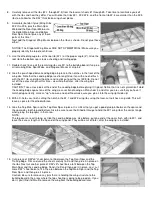
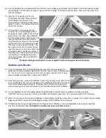
61. Cut two pieces of 1/2" balsa triangle to glue onto the back of the firewall to
reinforce the firewall-to-fuselage joint (see full-size plan). Cut notches in the
triangle where necessary to clear the blind nuts and pushrod hole. Glue the
triangles firmly in place.
62.
Glue the laser-cut balsa Tank Floor into the nose. The Tank Floor should sit flat on
the ledges created by the Fuselage Doublers, with the front of the Tank Floor up
against the back of Firewall.
63.
Glue in the laser-cut balsa Windshield in place.
64.
Lightly block sand the Hatch area to remove any bumps, glue spots, or mismatch between the fuselage sides, the doublers
and the top of the firewall. Be careful not to sand a curve in the fuselage sides which would cause an unsightly gap when
the Hatch is installed.
65.
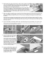
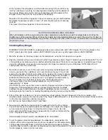
Locate the laser-cut plywood Hatch. Inspect both sides and choose the best looking side for the top. Draw guidelines on the
bottom of the Hatch for the location of the Hatch Tongue. The guidelines should be 1/4" in from each side, and 3/8" down
from the back end of the Hatch (see full-size Plan Sheet 1). Glue the laser-cut plywood Hatch Tongue in place on the
bottom of the Hatch.
66.
Tape the Hatch in place on the fuselage. Using the hole in the Hatch as a guide, drill a 1/16" dia. pilot hole in the top edge
of the firewall. Screw the Hatch down with a #2 x 3/8" Sheet Metal Screw and #2 Flat Washer.
67.
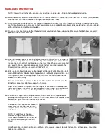
Two pieces of 3/16" o.d. x36" Large Nylon Pushrod Tubing are provided for
making the outer casing of the Elevator and Rudder Pushrods. Cut one piece for
the elevator pushrod to an overall length of 26-1/2". The piece for the rudder
pushrod will be cut off later in Step 69, so leave it full length for now.
Study the fuselage top and side views on full-size Plan Sheet 1 to familiarize
yourself with the proper location for each pushrod. Make a mark at 4-3/4" from
one end of each outer casing - this will be the servo end of the tube that sticks out
in front of former F-3. Feed each tube into place in the fuselage, starting from the
front and sliding them into the proper holes in the formers.
When you've got both tubes properly positioned, glue them permanently to all the
formers with Thick CA.
68.
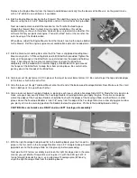
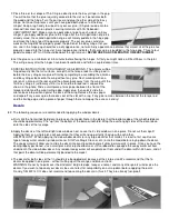
Cut two 5" long pieces of the 1/8" o.d. Small Nylon Pushrod Tubing from the 20" long piece provided (save the remainder
for the throttle pushrod - see Step 70). These will be the Pull-Pull Cable Guides. Glue them in place in the slots in the aft
end of the Fuselage Bottom Rear. Note that the rear ends of the tubes should be outside the fuselage, while the front ends
of the tubes should be on the inside.