


9
Very similar to the way a tree branch in a fast-flowing stream creates swirls or vortices in the
downstream flow, Figure A shows the alternating vortices (1) shed by the bluff body (2) inside
every InnovaMass. These vortices flex the instrument piezoelectric sensor tab (3), producing a
frequency output that is directly proportional to the flow rate.
Multivariable mass flow is achieved when a temperature sensor (4) is immersed in the flow
stream to measure the temperature of the flowing gas, liquid or steam. Simultaneously, a pressure
sensing port (5) leads up to an isolated pressure transducer.
MassBalance™ Sensor
Figure B takes a close-up view of (3) in Figure A above. This cutaway view of the sensor features
our patented MassBalance technology which works mechanically with DSP (Digital Signal
Processing) to cancel out external vibration influences. The MassBalance sensor has two sensing
beams (1 a & 1 b) isolated from each other by a mechanical ground (2). A piezoelectric crystal is
mounted inside the vortex-sensing beam (1 b) in a cantilevered (fixed at one end) fashion in the
flow path for sensing vortices shed from the bluff body. A second piezoelectric crystal is mounted
in a vibration-sensing beam (1 a), for sensing external vibrations only, extending in a cantilevered
fashion away from the vortex-sensing beam. The vortices formed by the flow around the shedder
bar push the sensor tab (3) “side-to-side,” flexing the piezoelectric crystals and causing them to
generate a voltage pulse with a frequency proportional to the flow rate.
The entire assembly is affected by vibration. Vibration affects sensor 1 a and 1 b equally, so the
two sets of piezoelectric crystals are configured to cancel out the vibration signal while only
sensor 1 b feels the “side-to-side” flow signal.
The waveforms above illustrate the vibration signals from the two opposing sensing beams inside
the MassBalance sensor. They are designed to be 180° out of phase from each other and when
added together effectively eliminate the vibration component. The sensor is mechanically
balanced and provides a very clean flow velocity signal where it undergoes advanced digital
signal processing. This clean velocity signal leads to enhanced noise and vibration rejection,
allowing measurement sensitivity at low flows.
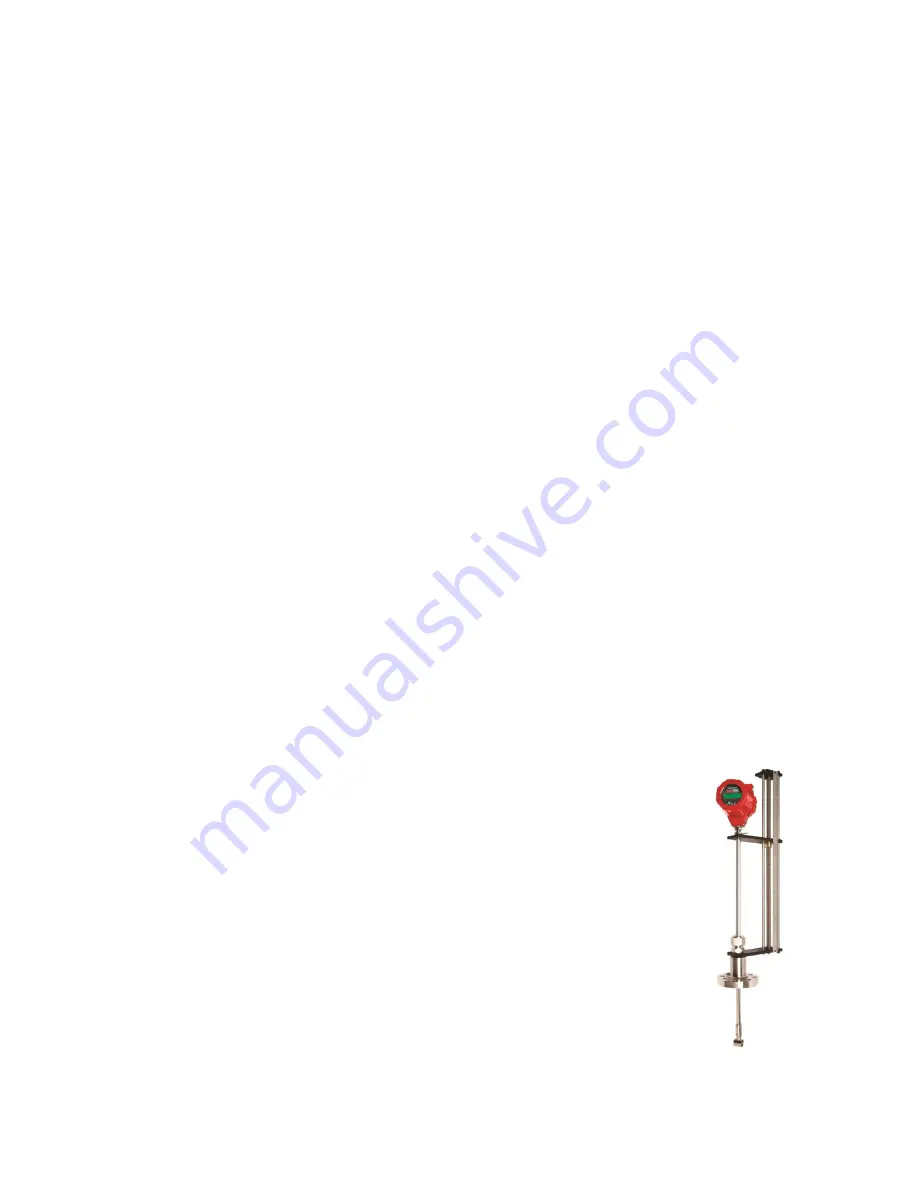
The Flexibility of Insertion
The 241i insertion vortex meter is an economical solution for applications from 2-
inch (50.8mm) pipes to 72 inches (1.8 M) in diameter and larger. Volumetric or
multivariable measurement is possible with a single pipe insertion point, greatly
reducing installation costs (Figure B). The 241i can be hot tapped into applications
with an optional probe retractor (shown right). More compact probe lengths are
available based on application requirements.
Raptor II OS Enhances Accuracy with FloPro™
Driven by Raptor II OS, the 241i insertion has a vastly improved flow profile
calculation using a proprietary application called FloPro. With all insertion point
velocity flow meters, knowing the flow profile inside the pipe or duct is key to stable
and reliable accuracy. Traditional insertion meters use a simple formula from Miller
that calculates flow profile assuming turbulent flow only.
FloPro makes no assumptions. It applies a sophisticated mathematical calculation for higher
resolution and understanding of flow profile. In addition to turbulent flow, FloPro calculates
Summary of Contents for InnovaMass 240i Series
Page 85: ...85 Appendix A Product Specifications ...
Page 86: ...86 ...
Page 87: ...87 ...
Page 88: ...88 ...
Page 89: ...89 ...
Page 90: ...90 ...
Page 91: ...91 ...
Page 92: ...92 ...
Page 93: ...93 ...
Page 94: ...94 ...
Page 95: ...95 ...
Page 96: ...96 ...
Page 111: ...111 ...
Page 112: ...112 ...
Page 113: ...113 ...