


Wide Beam Transmission
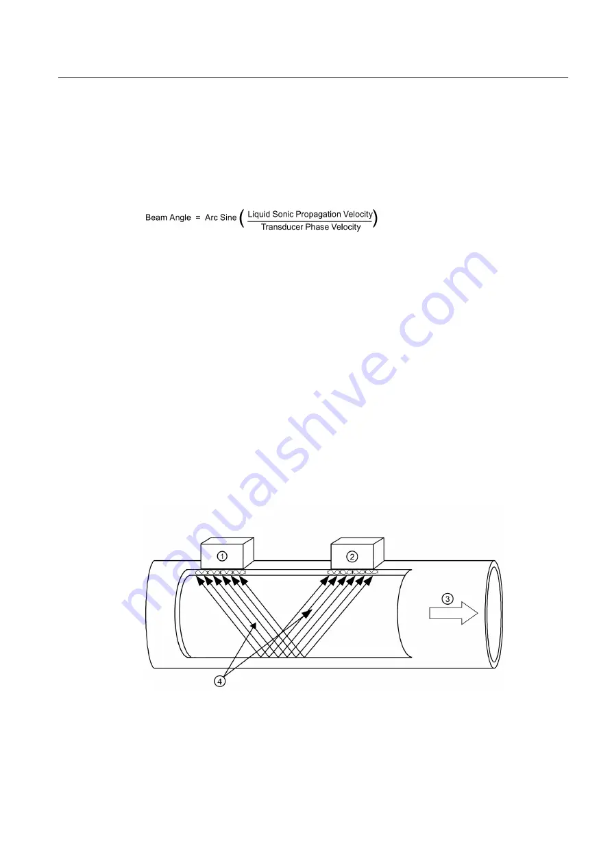
As shown in the figure below, an ultrasonic sensor induces an axial sonic beam within the wall
of the pipe. These vibrations spread along the pipe wall and then enter the liquid in the form
of a Wide Beam wave front traveling at an angle to the main pipe axis. The wide beam "rains"
over the receiving sensor. The wide coverage of the receiver is necessary because the angle
of the sonic beam is related to the liquid’s sonic propagation velocity by Snell’s Law.
According to this formula, it can be stated that as the liquid sonic propagation velocity changes
so will the angle between the sonic beam and the flow stream.
Therefore, a significant liquid sonic velocity shift could deflect a "narrow" beam transmission
away from the receiving sensor entirely. The upstream vs. downstream transit-time difference
will also be affected by the changing (or refracting) beam angle. This makes it necessary for
systems to continuously compute this angle, since it is subject to varying degrees of refraction.
The flowmeter derives the angle by knowing the fixed position of the sensors, the dimensions
of the pipe and the measured transit-time. Therefore, the flowmeter computes the beam angle
relative to the axis of the pipe.
Flow Calibration Factor
Normally, the flow stream is in line with the axis of the pipe. On this basis, the calibration factor
of a clamp-on ultrasonic flowmeter is proportional to the cosine of the beam angle relative to
the pipe axis. However, this reveals that if the angle of flow stream is not in line with the pipe
axis, the flow calibration factor could be compromised. This most often occurs when the sensor
mounting location is within close proximity of a bend or other pipe obstruction. It is
recommended that, whenever possible, mount sensors on the longest available straight run
of pipe and also use Reflect Mode mounting (as shown below).
①
Upstream Sensor
②
Downstream Sensor
③
Flow Direction
④
Wide Beam transmissions exchanged between the Upstream and Downstream sensors
Description
3.3 Theory of Operation
FUP1010 IP67 Portable Flowmeter
Operating Instructions, 02/2010, A5E02951522A Revision 01
17
Summary of Contents for SITRANS FUP1010
Page 2: ......
Page 66: ......
Page 136: ......
Page 138: ......
Page 150: ......
Page 153: ...1010WP 7 21614 C ...
Page 154: ...1010WP 7 21614 C ...
Page 155: ...1010WDP 7 21614 C ...
Page 156: ...1010WDP 7 21614 C ...
Page 157: ...1010WP 8 21614 C ...
Page 158: ...1010WDP 8 21614 C ...
Page 159: ......
Page 161: ...1012FP 8 DIRECT MODE REFLECT MODE INSTALLED ON PIPE 21614 C ...
Page 162: ...1011PPS 8 TRANSDUCER PART NUMBER L H W NET WT PAIR X Z 21614 C SIZES A B C D SIZE E ...
Page 163: ...21614 C ...
Page 164: ......
Page 165: ......
Page 166: ......
Page 167: ......
Page 168: ...21614 C ...
Page 169: ...21614 C ...
Page 170: ...21614 C ...
Page 171: ...21614 C ...
Page 172: ...21614 C ...
Page 173: ...21614 C ...
Page 174: ...21614 C ...
Page 175: ...1015BC 1W 8 21614 C ...
Page 176: ......
Page 177: ...21614 C ...
Page 178: ...21614 C ...
Page 179: ...1012TP S 8 OUTLINE DIMENSIONS REFLECT MODE DIRECT MODE 1012TP S SERIES 21614 C MOUNTING TRACK ...
Page 180: ...REFLECT MODE DIRECT MODE 21614 C ...
Page 181: ...21614 C ...
Page 182: ...1015BC 1 8 21614 C ...
Page 183: ...21614 C INPUT OUTPUT TERMINALS 1015WP T10 8 ...
Page 184: ...21614 C INPUT OUTPUT TERMINALS 1015WP T26 8 ...
Page 185: ......
Page 186: ......
Page 187: ......
Page 188: ......
Page 190: ...DUAL HEAD CONFIGURATION 21614 C IN LINE CONFIGURATION FLOW ...
Page 191: ......
Page 192: ......
Page 194: ......
Page 204: ......
Page 206: ......
Page 207: ......