Siemens SITRANS FUP1010 Operating Instructions Manual Download Page 115

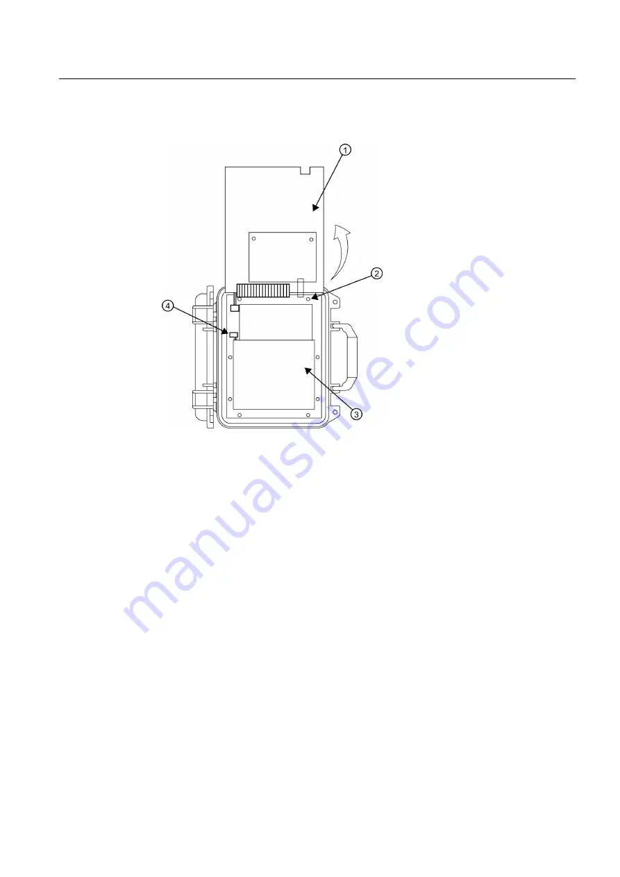
5. Pry up faceplate and gently lift upwards. Tilt faceplate back and rest it securely so that the 

inside of the flowmeter is accessible but that there is no pressure on the wiring harnesses.

Faceplate tilted up and back

Battery Cover Plate

Battery Cover Screws (8)

Battery Connector P2

Figure 9-2

Battery Cover Removal

6. Remove 8 screws securing the battery cover. Set aside screws.
7. Disconnect pendant battery connector (J2). Note that it is a keyed-type plug.

Maintenance and service
9.2 Replacing the battery

FUP1010 IP67 Portable Flowmeter

Operating Instructions, 02/2010, A5E02951522A Revision 01

113

Summary of Contents for SITRANS FUP1010

Page 1: ...Ultrasonic flowmeters SITRANS FUP1010 IP67 7ME3510 Portable Flowmeter Operating Instructions February 2010 SITRANS F ...

Page 2: ......

Page 3: ...g Instructions 02 2010 A5E02951522A Revision 01 Introduction 1 Safety notes 2 Description 3 Installing mounting 4 Connecting 5 Commissioning 6 Functions 7 Alarm error and system messages 8 Maintenance and service 9 Troubleshooting 10 Technical data 11 Appendix A Appendix B ...

Page 4: ...ocumentation for the specific task in particular its warning notices and safety instructions Qualified personnel are those who based on their training and experience are capable of identifying risks and avoiding potential hazards when working with these products systems Proper use of Siemens products Note the following WARNING Siemens products may only be used for the applications described in the...

Page 5: ...s 20 4 4 Charging the Battery 20 5 Connecting 23 5 1 Transmitter Wiring 23 5 1 1 Connecting Battery Power 23 5 1 2 Connecting AC Power 28 5 2 Sensor Wiring 28 5 2 1 Preliminary Installation Procedures 28 5 2 2 Sensor Identification and Selection 32 5 2 3 Setting the Parameters 33 5 2 4 Reflect Mount 37 5 2 5 Direct Mount 41 5 2 6 1012T Mounting Tracks 48 5 3 Zero Flow Adjust Menu 60 6 Commissionin...

Page 6: ... the battery 111 9 3 Battery Disposal 114 9 4 Technical support 114 9 5 Return procedures 115 10 Troubleshooting 117 10 1 Troubleshooting 117 10 2 F4 Reset Procedure 118 10 3 Test Facilities Graph Screen 119 10 4 Site Setup Data 128 11 Technical data 135 11 1 Technical Data 135 A Appendix 137 A 1 Certificates 137 A 2 Accessories and spare parts 137 A 3 I O Connections and Wiring 137 A 4 Site Setup...

Page 7: ... Table 10 1 Troubleshooting Tips 117 Table 10 2 Description of Graph Screen Text Display Parameters 127 Table 10 3 Hot Key Summary 127 Table 10 4 Site Setup Menu Items 129 Table 11 1 Performance Specifications 135 Table A 1 Part Numbers and Connection Data 137 Table A 2 2 Channel 2 Path Input Output Terminal Block Wiring 137 Figures Figure 3 1 Weatherproof Case shown open 11 Figure 4 1 Power Adapt...

Page 8: ...gure 5 23 Direct Mount 180 opposed with Mounting Tracks 54 Figure 5 24 Direct Mount Roller Chain 56 Figure 5 25 Wrapping the Mylar Spacing Guide around pipe End View 57 Figure 5 26 Finding the Halfway Distance 57 Figure 5 27 Track Rail Alignment 58 Figure 5 28 REF and Number Index Pin Locations 59 Figure 6 1 Key Pad 67 Figure 6 2 Typical Installation Menu Screen Example 68 Figure 7 1 Sensor Mounti...

Page 9: ...TRANS F literature CD For additional items refer to your packing slip Inspection 1 Check for mechanical damage due to possible improper handling during shipment All claims for damage are to be made promptly to the shipper 2 Make sure the scope of delivery and the information on the type plate corresponds to the ordering information 1 3 History The contents of these instructions are regularly revie...

Page 10: ...s are available on the CD ROM shipped with the device and on the Internet on the Siemens homepage where further information on the range of SITRANS F flowmeters may also be found Product information on the internet http www siemens com flow Worldwide contact person If you need more information or have particular problems not covered sufficiently by the operating instructions please get in touch wi...

Page 11: ... Instrument safety standards The device has been tested at the factory based on the safety requirements In order to maintain this condition over the expected life of the device the requirements described in these Operating Instructions must be observed CAUTION Material compatibility Siemens Flow Instruments can provide assistance with the selection of sensor parts However the full responsibility f...

Page 12: ...tion of excessive heat where internal pressure may cause the cell to rupture Thus the following basic precautions should be observed when handling and using lithium batteries Do not short circuit recharge or connect with false polarity Do not expose to temperature beyond the specified temperature range or incinerate the battery Do not crush puncture or open cells or disassemble battery packs Do no...

Page 13: ...zes very straight forward and easy The sensors deliver true multi parameter measurements i e volume flow and temperature The flowmeter has a degree of protection of IP67 Note This operating Instructions manual applies to the following FUP1010 IP67 weather proof operating systems Version 3 02 00K and later and version 4 03 00 and later Portable Configurations The FUP1010 weatherproof single and dua...

Page 14: ...easured using the Reflexor mode Dual channel portable systems allow operation with one transit time channel and one Reflexor channel measuring flow on the same pipe 3 2 Applications Measurement of liquids SITRANS F flowmeters are designed for measurement of a variety of liquids and gases The transmitters are multi parameter devices offering accurate measurement of mass flow volume flow density and...

Page 15: ... Considering typical liquid flow transit time differences ranging from 1x10⁴ to 1x10⁶ psec the flowmeter is capable of providing an exceptional turn down ratio The flowmeter also incorporates a correlation technique which enables the system to detect very high flow velocities with the same high degree of resolution The ultrasonic sensors are designed with sufficient beam divergence characteristics...

Page 16: ...ncreases toward the center axis of the flow stream Fluid velocity near the axis of the flow stream tends to be greater The Reynolds number is then computed as follows where viscosity cS cP density cS kinematic viscosity cP absolute viscosity The flowmeter then uses this computation of Reynolds number to compensate the raw flow velocity for conditions of laminar or turbulent flow profile as defined...

Page 17: ...d with an API 60o F as well as Viscosity 60o F This information can be keyed into a lookup table within the flowmeter This table then serves as a reference for dynamically inferring the liquid properties as different liquid batches enter the flow transducer The lookup function for this table will also interpolate and extrapolate for values between and outside the table values 2 Based on FLOWRAW an...

Page 18: ...w Pipe A 2 Path 2 Path flowmeters use two measurement channels to achieve a single output via a virtual third channel The resultant data is the average of the two channels Only clamp on or in line transit time operation is allowed Benefits include highest available precision and enhanced immunity to distorted flow profile conditions Sensor Path 1 Average Path 1 Path 2 2 Sensor Path 2 Pipe front vi...

Page 19: ...nce it is subject to varying degrees of refraction The flowmeter derives the angle by knowing the fixed position of the sensors the dimensions of the pipe and the measured transit time Therefore the flowmeter computes the beam angle relative to the axis of the pipe Flow Calibration Factor Normally the flow stream is in line with the axis of the pipe On this basis the calibration factor of a clamp ...

Page 20: ...change of sonic signals occurs by reflection off the far pipe wall as shown above the average beam versus stream angle will be equivalent to that of an axial flow stream Description 3 3 Theory of Operation FUP1010 IP67 Portable Flowmeter 18 Operating Instructions 02 2010 A5E02951522A Revision 01 ...

Page 21: ...ovide adequate protection to minimise any risk of contact with hot surfaces WARNING Prevent personal injuries by assuring that operation below pressure guards cannot take place if working with vacuum or fluids boiling readily 4 2 Use according to specifications Use according to specifications covers Use within technical limits Consideration of liquid specifications and references Consideration of ...

Page 22: ...uld be smooth and if necessary free of paint Avoid pressure reduction components upstream Avoid mounting on or near weld seams Additonal Requirements for Liquid Applications Pipe must be full to achieve proper operation 4 4 Charging the Battery The flowmeter has an optional battery charger that operates from a 100 110 or 220 VAC 50Hz or 60Hz power source It has a universal power input that require...

Page 23: ...dapter Battery Charger Table 4 1 Power Cord Codes Assembly P N POWER CORD Plug Std Rating 1015BCA 1 CEE 7 7 10A 230VAC 1015BCC 1 A5 3112 10A 250VAC 1015BCD 1 BS 1363 5A 240VAC 1015BCJ 1 JIS 8303 12A 125VAC Installing mounting 4 4 Charging the Battery FUP1010 IP67 Portable Flowmeter Operating Instructions 02 2010 A5E02951522A Revision 01 21 ...

Page 24: ...1015BCK 1 NEM 5 15P 10A 120VAC 1015BCL 1 SEV 1011 10A 250VAC Installing mounting 4 4 Charging the Battery FUP1010 IP67 Portable Flowmeter 22 Operating Instructions 02 2010 A5E02951522A Revision 01 ...

Page 25: ...um batteries have to be formed to deliver their optimum operating time This is accomplished by performing a minimum of two complete discharge charge cycles Note To remove replace or dispose of the internal battery pack refer to Maintenance and Service Page 111 in the instruction manual To Produce a Charge Discharge Cycle 1 Press the ON keypad to turn the flowmeter ON without connecting an external...

Page 26: ... 7ME39403BC20 Power Adapter Battery Chargers are designed specifically for use with the portable flowmeters The 1015BB Battery Pack uses a special Lead Acid battery design that features a deep discharge cycle for extended operation CAUTION Do not use any other external Battery Charger Pack combination with the flowmeter unless reviewed and pre approved by Siemens CAUTION Do not leave the Battery C...

Page 27: ...ette Connector Adapter Cable 1 22 meters Extended 4 ft Figure 5 1 External Battery Pack Charging the External Battery Pack Connecting 5 1 Transmitter Wiring FUP1010 IP67 Portable Flowmeter Operating Instructions 02 2010 A5E02951522A Revision 01 25 ...

Page 28: ...ve place the 1015BB Battery Pack on a flat surface such as a table or bench Ensure that an AC outlet is available at or close to the location 2 Open the Battery Pack cover Leave it open for the entire charge time Connecting 5 1 Transmitter Wiring FUP1010 IP67 Portable Flowmeter 26 Operating Instructions 02 2010 A5E02951522A Revision 01 3 Plug the 1015BCK 2 Adapter Battery Charger USA 7ME39403BC10 ...

Page 29: ...ure 5 2 1015BCK 2 and 1015BCA 2 Battery Chargers Note A LOBAT flag appears on the flowmeter graphic screen when the remaining battery operating time is less than 20 minutes Connecting 5 1 Transmitter Wiring FUP1010 IP67 Portable Flowmeter Operating Instructions 02 2010 A5E02951522A Revision 01 27 ...

Page 30: ...arger input connector 3 Plug the Power Adapter Charger AC plug into an AC power outlet AC Cord Input Input Output Connector Connect to Rear Panel Power Input Connector RS 232 Port Flow Sensor Channel 2 Battery Status Indicator Flow Sensor Channel 1 Auxiliary Power Battery Charger Input Figure 5 3 Power Adapter AC Charger for Dual Channel Flowmeter 5 2 Sensor Wiring 5 2 1 Preliminary Installation P...

Page 31: ...ts abnormal flow profile conditions such as cross flow within the flow stream Reflect mount supports the AutoZero function which zeroes the flowmeter automatically without user participation In addition Reflect mount may be the only possibility if conditions do not allow access to the opposite side of the pipe Direct mount provides a shorter sonic beam path This usually improves performance with s...

Page 32: ... a throttling valve a mixing tank the discharge of a positive displacement pump or any other equipment that could possibly aerate the liquid The best location will be as free as possible from flow disturbances vibration sources of heat noise or radiated energy 3 Avoid mounting the sensors on a section of pipe with any external scale Remove all scale rust loose paint etc from the location 4 Do not ...

Page 33: ...al pipe flowing in a downward direction make sure there is sufficient back pressure in the system to maintain a full pipe Dual Path Reflect Mount Dual Path Direct Mount Figure 5 6 Sensor Alignment Horizontal Plane Preparing the Pipe 1 Pick a mounting location with the longest straight run You must have easy access to at least one side of your pipe The pipe at the mounting location must remain full...

Page 34: ...ipe Pipe Cleaned Areas Figure 5 7 Pipe Surface Preparation 4 Clean an area 13 mm 1 2 inch on either side of the sensors 5 Clean an additional 13 mm 1 2 inch along the length of the sensors 5 2 2 Sensor Identification and Selection Sensor identification The sensor part number located on the front face provides a detailed identification For example the Part Number 1011HNFS D1H UT1 S2 means Model Siz...

Page 35: ...fore you can select a sensor model Refer to Transmitter Wiring Page 23 Before selecting sensors proceed to Setting the Parameters Page 33 and perform the preliminary programming procedures 5 2 3 Setting the Parameters Select Language and Units Note Before creating a site select a language and then English or Metric units from the Meter Facilities menu To select English or metric units 1 In Meter T...

Page 36: ...own Arrow to highlight Create Name Site Press Right Arrow to enter a Site name 3 Press ENT to create Site name e g ABC Insert desired name 8 characters max Note To select letters Press Right Arrow to cursor and then press Up Down Arrows to select letters Press ENT when done Note To select English or metric units In Meter Type Menu scroll to Meter Facilities Menu Press Right Arrow and select prefer...

Page 37: ... parameters will appear in menu cells Press Right Arrow and scroll to desired pipe size Press ENT Enter dimensions manually if pre programmed dimensions do not match application 5 Press the Left Arrow and return to the main menu Select a Liquid Class 1 Press the Down Arrow and scroll to Application Data 2 Press the Right Arrow to select Liquid Class 3 Press the Right Arrow again and scroll to desi...

Page 38: ...itions Options Definitions Fully Developed Fully developed flow as would be expected for very long straight pipe runs or installation downstream of a flow condition 1 Elbow Single 90 degree Elbow upstream of sensor installation Dble Elbow Double out of plane Elbows upstream of sensor installation Dble Elbow Double in plane Elbows upstream of sensor installation Valve Not available at this time Exp...

Page 39: ...be mounted 6 After sensors are mounted scroll to Install Complete and select Install Select based on type Select based on size After sensor is mounted select Install 5 2 4 Reflect Mount Reflect Mount using E Z Clamp and Spacer Bar The EZ Clamp is a quick and easy way to securely mount sensors on any pipe The spacer bar eliminates manual spacing measurements and provides rigidity for mounting the s...

Page 40: ...e sensors will be mounted Check to ensure that you have a matched set of sensors They both should have the same S N number but marked with either an A or B e g 100A and 100B 2 Degrease the surface and remove any grit corrosion rust loose paint etc 3 Assemble the sensors to the spacer bar with the cable connectors facing away from each other as shown above The spacer bar is attached to a sensor usi...

Page 41: ...two areas you marked by degreasing the pipe surface Remove any grit corrosion rust loose paint or surface irregularities with the abrasive pipe conditioning material provided 8 Remove the sensor from the spacer bar that was attached through the REF hole Attach the EZ clamp to the sensor under the spring clip The adjusting nut knob should be pointing up and on the side opposite the spacer bar Unscr...

Page 42: ...ipe and the sensor contacts the pipe at the white dot just under the front label Ensure that there is equal space on either side of the dot between the edges of the sensor and pipe 13 Repeat Steps 7 8 and 9 for the second sensor leaving it attached to the spacer bar At the same time that you place it in the middle of the second prepared pipe area secure the spacing bar to the previously mounted se...

Page 43: ...hod ensures that sensors will align exactly 180 from each other and remain spaced the proper distance apart For Direct Mode mounting a spacer bar is used to establish the distance between sensors and a spacing guide is used to locate the sensors at the nine o clock and three o clock positions Should the distance between sensors be beyond the span of a spacer bar a measuring tape can be used The My...

Page 44: ...aised areas seams etc With a pencil or chalk mark a generous area around all sides of the sensor Remove the sensor 3 Prepare the area you marked by degreasing the surface and removing any grit corrosion rust loose paint or surface irregularities with the abrasive pipe conditioning material provided Connecting 5 2 Sensor Wiring FUP1010 IP67 Portable Flowmeter 42 Operating Instructions 02 2010 A5E02...

Page 45: ... lengthwise 3 mm 1 8 inch bead of coupling compound across the center of the sensor emitting surface Cable Connector Front Edge Angled Edge Emitting Surface Sensor Coupling Compound Figure 5 16 Sensor 6 Place sensor at the center of the pipe in the middle of one of the areas you have cleaned Ensure that the cable connector is facing away from where the other sensor will be placed Connecting 5 2 Se...

Page 46: ...sets of holes for securing the spacer bar When using the EZ Clamp assembly use the lower set of holes when attaching the spacer bar 11 Do not apply any couplant to the second sensor First attach the spacer bar assembly with the second sensor attached to it to the mounted sensor by inserting an index screw through the REF hole and into the lowest hole on the sensor Tighten the screw 12 Visually che...

Page 47: ...dot and draw a line across the dots see B below Set spacer bar aside Sensor 1 Sensor Edge Line Pipe Spacer Bar Place dot below white dot Dot Sensor 2 Line Mylar Spacing Guide Connecting 5 2 Sensor Wiring FUP1010 IP67 Portable Flowmeter Operating Instructions 02 2010 A5E02951522A Revision 01 45 ...

Page 48: ...e Mylar spacing guide and lay it out on a flat surface Either measure the exact distance half way between the overlap edge and the mark at the overlap or fold the guide from the overlap edge to the overlap mark and draw a line at the fold halfway point Overlap Edge Mark on Spacing Guide Mark or fold exactly at half way point Circumference Figure 5 18 Finding the Halfway Distance 19 Reinstall the s...

Page 49: ...sition it was in and retape it to the pipe 23 Attached the EZ Clamp to the sensor under the spring clip Unscrew the knob until it s at the stop 24 Apply a continuous lengthwise 3mm 1 8 inch bead of coupling compound across the center of the sensor emitting surface 25 Hold the sensor in place and bring chain around pipe and attach to the closest link on the EZ Clamp S hook 26 Tighten the adjusting ...

Page 50: ...o 121 C 250 F The assembly consists of lightweight aluminium track rails with integral sensor clamping screws Attached index pins enable positive locating of the sensors at fixed spacing locations Roller chains and tension screws secure the assembly to the pipe The 1012TP mounting tracks support both Direct and Reflect mounting modes The flowmeter recommends the appropriate sensors mounting track ...

Page 51: ...numbers plus the designation of the Number Index Sensor type size and mounting mode selection Automatic selection of mounting track part number and Number Index Connecting 5 2 Sensor Wiring FUP1010 IP67 Portable Flowmeter Operating Instructions 02 2010 A5E02951522A Revision 01 49 ...

Page 52: ...f the sensors see in figure below Tension Screw Pipe To SITRANS F 1010 Flowmeter Ultrasonic Couplant 1012C Series Cable Number Index hole pin Sensor Clamp 1012TP Series Mounting Track Upstream and Downstream Sensors Flow direction REF Hole Index Pin Figure 5 21 Reflect Mount with Model 1012TP Mounting Track Side View 3 Place the track rail assembly on the top surface of the pipe at the location wh...

Page 53: ...Rotate the track into the position that was just cleaned Insert the index pin into the REF hole 9 Select a sensor and apply a thin band of couplant compound to the sensor s emitting surface 10 Place the sensor between the track rails slightly behind the pin and under the clamping screw assembly Slide it forward until it butts up firmly against the reference pin 11 Once the sensor is in place secur...

Page 54: ...nting Tracks and a spacer guide is the recommended way to mount sensors in the Direct Mode This method ensures that sensors will align exactly 180 from each other and remain spaced the proper distance apart The Direct Mount configuration uses a set of two track rail assemblies one for each sensor installed 180 apart on the pipe The set includes Connecting 5 2 Sensor Wiring FUP1010 IP67 Portable Fl...

Page 55: ...has number index holes for inserting an index pin to position the other sensor Note A pin will be inserted into the hole designated by the Number Index on the Direct Mode track rail to position one of the sensors see in figure below Connecting 5 2 Sensor Wiring FUP1010 IP67 Portable Flowmeter Operating Instructions 02 2010 A5E02951522A Revision 01 53 ...

Page 56: ...pter Flow direction Sensor Clamp 1012TP Series Mounting Track D 1011PPS Series Sensor Upstream REF Hole Index Pin 1012TP Series Mounting Track R Ultrasonic Couplant Figure 5 23 Direct Mount 180 opposed with Mounting Tracks Connecting 5 2 Sensor Wiring FUP1010 IP67 Portable Flowmeter 54 Operating Instructions 02 2010 A5E02951522A Revision 01 ...

Page 57: ...ight angle adapter This adapter should be installed before placing the sensors in the tracks 3 Prepare pipe for the track mounts by degreasing the surface if needed and removing any grit corrosion rust loose paint or surface irregularities with the abrasive pipe conditioning material provided 4 If this is a horizontal pipe place the track rail assembly against the pipe While holding track place se...

Page 58: ...l Assembly 1 Pipe Track Rail Assembly 2 Sensor 2 Figure 5 24 Direct Mount Roller Chain Note For a vertical pipe installation use a tie tape or bungee cord to hold the two tracks in place while chaining 6 Finger tighten the chain Tension Screw to secure the chain and tracks to the pipe Connecting 5 2 Sensor Wiring FUP1010 IP67 Portable Flowmeter 56 Operating Instructions 02 2010 A5E02951522A Revisi...

Page 59: ...ing end Trim material from inner edge if necessary Mylar Spacing Guide 8 cm 3 inches Overlapping Edge Figure 5 25 Wrapping the Mylar Spacing Guide around pipe End View 2 Remove the spacer guide Measure or fold spacer guide to find its halfway distance Mark a center line and then tape spacer guide to pipe Overlap Edge Mark on Spacing Guide Mark or fold exactly at half way point Circumference Figure...

Page 60: ...nt 4 Loosen the chains enough to allow you to rotate the track assembly until the center of one track aligns with the center line on the Spacer Guide and the center of the other track aligns at the point where the Spacer Guide ends meet The tracks should now be 180 apart Tighten both chains but not too tight Connecting 5 2 Sensor Wiring FUP1010 IP67 Portable Flowmeter 58 Operating Instructions 02 ...

Page 61: ... s stopped by the pin Move sensor clamping screw over the sensor and tighten 5 Using a pencil or chalk mark a generous area around where the sensors contact the pipe 6 Release the tension on the sensors and remove them 7 Loosen the chains and rotate the track assembly on the pipe so you can gain access to the areas marked 8 Prepare the areas you marked by degreasing the surface if needed and remov...

Page 62: ...ure proper zero flow compensation The following paragraphs describe each method and when they should be used AutoZero When the 1011HP sensors are mounted in the Reflect Mode configuration the AutoZero routine is automatically invoked at the end of the Initial Makeup Flow does not have to be stopped to perform AutoZero since only the pipe wall signal is used in determining the zero offset and not t...

Page 63: ...ounted in the Reflect Mode configuration and is recommended for applications which experience large temperature extremes Note Invoking ZeroMatic will clear any existing fixed or memorized zero offset If any zero offset remains after flow is stopped an Actual Zero can be performed without interrupting ZeroMatic operation To disable ZeroMatic invoke it again but then press Left Arrow to abort the in...

Page 64: ... Down transducer cable location Mount Down transducer with its cable in the Up transducer cable location When remounting the transducers couple them to the pipe properly Press ENT after re installing the transducers 6 The flowmeter measures the negative flow rate briefly then beeps and repeats the prompt 7 Now remount the transducers for normal operation in their original orientation When remounti...

Page 65: ... ENT When the Initial Makeup of ZeroMatic is complete the screen will return to the Pick Install Xdcr menu and automatically highlight Operation Adjust which is the next menu cell To disable the ZeroMatic function 1 Select the Install Xdcr menu cell from the Dual Path Flow menu 2 Scroll down to the Zero Flow Adjust menu cell by pressing Up Down Arrow Note The highlighted ZeroMatic menu item is the...

Page 66: ......

Page 67: ...arry dangerous high voltage CAUTION Confirm that one of the following power sources is connected internal battery pack external battery pack or Power Adapter Battery Charger 1 Apply power 2 Within 10 seconds of power up the main display will become active and a typical Siemens graphic will appear briefly The screen also identifies the software version of the unit as shown below Software operating ...

Page 68: ...dy to report flow Press the Menu key again to display flow 6 3 Navigating the Menu Installation Menu Navigation The Installation Menu Chart is a multi level structure divided into three columns from left to right Level A lists the major menu categories Level B list the menu cells associated with Level A You can enter data into Level B menu cells that are display parameters in a column at the right...

Page 69: ...ws Same as Left and Right arrows Scrolls option lists and graphic display screen CLR Erases data or selects list options Numbers 0 9 Use to type numeric data Decimal Point Use for decimal points in numeric data Math Operators 4 function math operations in numeric entry cells F Keys 1 2 and 3 Caution System Reset Key use during power up CTL and ALT Used as shift keys for alternative key functions D...

Page 70: ...Type 2 Channel Flow Channel 1 2 Clamp on FastStart Setup Pick Pipe Class Enter From List Dual Path Flow Reflexor Select Pipe N A Ch 1 2 Flow Install Xdcr Transducer Model Enter From List Ch 1 2 Flow Transducer Size Enter From List Thickness Gauge Xdcr Mount Mode Enter From List Spacing Offset Enter From List Number Index View Only Spacing Method View Only Ltn Value in View Only Install Complete No...

Page 71: ...ist Estimated Vs MS Numeric Entry Viscosity cS Numeric Entry Density S G Numeric Entry Temp Range Enter From List Pipe Config Enter From List Anomaly Diams Numeric Entry Install Xdcr Transducer Model Enter From List Transducer Size Enter From List Xdcr Mount Mode Enter From List Spacing Offset Enter From List Number Index View Only Spacing Method View Only Ltn Value in View Only Install Complete N...

Page 72: ... List StripChart Clear No Yes Logger Setup Logger Mode Enter From List Logger Data Enter From List Logger Interval Enter From List Logger Events Enter From List Display Logger Enter From List I O Data Control Analog Out Setup Enter From List Relay Setup Relay 1 2 Analog Inp Setup Enter From List Diagnostic Data Flow Data Enter From List Application Info Enter From List Liquid Data Enter From List ...

Page 73: ...Trim Trim Io1 Operate Trim 4mA Trim Io2 Operate Trim 4mA Trim Vo1 Operate Trim 2V Trim Vo2 Operate Trim 2V Trim Pgen1 Operate Trim 1Khz Trim Pgen2 Operate Trim 1Khz RTD Calibrate RTD1 Factory User Cal RTD2 Factory User Cal Clock Set Date MM DD YY Edit Date Time HH MM Edit Time RS 232 Setup Baud Rate Enter From List Parity Enter From List Data Bits 7 8 Line Feed Yes No Network ID Numeric Entry Comm...

Page 74: ...sion View Only Battery Capacity View Only Reset Data Time View Only mm dd yy hh mm ss Op System P N View only Checksum View Only Code View only System Time View Only mm dd yy hh mm ss Language Enter From List Commissioning 6 4 Installation Menus FUP1010 IP67 Portable Flowmeter 72 Operating Instructions 02 2010 A5E02951522A Revision 01 ...

Page 75: ...llows you to select the rate units the flowmeter uses to report volumetric or mass flow If you select mass units the flowmeter uses the specific gravity parameter to convert volumetric flow to mass flow The default in English Units for liquid is Gallons To select a Volumetric or Mass unit 1 Press the MENU key and Meter Type will be highlighted 2 Press the Right Arrow to Dual Path Flow and then pre...

Page 76: ...ative flow Adds to positive total subtracts from reverse total Note NETFLOW default is best for applications where there may be zero flow for long periods It minimizes false Totalizer register increments due to data scatter Press the Down Arrow to accept the default setting Selecting Totalizer modes 1 Press the MENU key and Meter Type will be highlighted 2 Press the Right Arrow to Dual Path Flow a...

Page 77: ...AR trigger would be F3 1 F1 F2 F3 F4 NOTOT Totalizer Freeze Invoking the NOTOT command disables the Totalizer Totalization will not resume until you repeat the Fn 2 key sequence When you activate NOTOT an N precedes the TOTAL symbol i e NTOTAL on the LCD Screen F1 F2 F3 F4 LAPTOT Totalizer snapshot The LAPTOT command freezes the Totalizer screen display However the flowmeter will continue to updat...

Page 78: ...updates the output data setup to reflect the change Span limits apply to both the analog outputs and the on screen stripchart The flow outputs operate as follows Vfo Spanned Volumetric The minimum and maximum flow rate entries establish the Vfo span The Max Flow menu cell sets 100 of span The Min Flow menu cell sets 0 of span Use signed numbers for bi directional spanning Note that negative revers...

Page 79: ...ow to Dual Path Flow and press ENT 2 Scroll to Span Set Cal and press Right Arrow 3 Highlight Span Data and press the Right Arrow 4 Highlight Max Flow and press Right Arrow to Input 100 flow rate numeric data for 20 mA Press ENT to store data 5 Scroll down to Min Flow Press Right Arrow to input 0 flow rate numeric data for 4 mA Press ENT to store data Input numeric flow data here Functions 7 2 Spa...

Page 80: ...s of logging time remaining For convenience sake the Display Logger command is essentially a duplicate of the menu cell in Logger Setup It sends Logger data to the graphic screen with or without line wrapping The Output Logger command sends data to an external device via the RS 232 serial port The Clear Logger command erases the entire Logger file 1 From the Meter Facilities menu access the Logger...

Page 81: ...uter or printer via the flowmeter s RS 232 Serial I O port This command is effective only after a successful install In addition you have to enable datalogging and select data items in the Logger Setup menu The flowmeter interfaces with most serial printers or personal computers for Logger printouts You must use the proper cabling between the flowmeter and the external device In addition you must ...

Page 82: ...er Control menu select Circular Memory 5 Press Right Arrow to access the Circular Memory option list 6 Move the cursor to Yes by pressing Up Down Arrow 7 To store selection press ENT 8 Lastly re enable the channels paths that you disabled earlier to begin logging Est LogTime Left Est LogTime Left is a view only menu cell that shows an estimate of the amount of Logger time remaining in hours and mi...

Page 83: ...nuous Fault condition Damping Control The flowmeter provides two different data output filter types Time Average and SmartSlew Time Average recommended integrates the instantaneous flow rate over a selectable time period Use the Time Average function when stability in flow reading is essential A value entered in seconds sets the time it takes the flowmeter to respond to a rate change The default i...

Page 84: ...ow rate falls below a specified level usually a very low rate It will prevent the possibility of data scatter a natural result of digital computation from causing false Totalizer accumulation during long non flowing periods Inspect the actual data scatter during zero flow conditions to find the proper Deadband setting for your application To edit Deadband default setting 0 000 1 From the Dual Path...

Page 85: ...tion Adjust menu and press Right Arrow 2 Scroll to the Memory Fault Set and press Right Arrow to access option list 3 Move the cursor down to Memory by pressing Up Down Arrow 4 To make selection press ENT 5 This moves the highlight to Memory Delay s Memory Delay s Selecting Memory Delay s activates the suppressed Memory Delay menu cell It allows you to specify the number of seconds that the flowme...

Page 86: ...overflow register This allows the relay to catch up when flow decreases enough Note Using the F1 key Totalizer clear command also clears all channel Totalizers plus the overflow register described in the last paragraph Relay 1 and 2 Function Assignments The flowmeter depending upon the model provides at least two alarm relays Please refer to the Appendix Page 137 for wiring details Relays respond ...

Page 87: ...ath Flow menu scroll down and highlight I O Data Control 2 Press Right Arrow and scroll down to Relay Setup 3 To access the Relay Setup option list press Right Arrow 4 Move the cursor to the desired Relay assignment by pressing Up Down Arrow 5 To store selection press ENT Repeat procedure for all other relays Functions 7 5 Setting Relays FUP1010 IP67 Portable Flowmeter Operating Instructions 02 20...

Page 88: ...s all memory left except for two conventional empty sites required for Datalogger use To view the amount of data memory bytes available press Right Arrow Memory Map Selecting YES for this item enables a snapshot display of current memory usage In this display the asterisk indicates a used block a space indicates a free block while a dash character indicates unused filler Defragment Selecting YES f...

Page 89: ...in proportion to an assigned data function Table 7 7 Analog Out Setup Data Categories Vfo Spanned volumetric mass flow Vfab Spanned unsigned flow magnitude Vs Spanned liquid sonic velocity Valc Receive signal amplitude Vaer Relative degree of liquid aeration cavitaion T1 Current liquid temperature Io Output Functions Assigning a function to the current output 1 From the Dual Path Flow menu scroll ...

Page 90: ...row 3 To store selection press ENT Note Refer to drawing 1010N 7 7 for Analog output connections Pgen Output Functions The Pgen analog output is a buffered TTL compliant pulse rate signal that varies linearly from 0 5000 Hz in relation to to a selected data function Assigning a function to the Pgen output 1 From the Analog Out Setup menu press Right Arrow to access the Pgen option list 2 Move the ...

Page 91: ...gh the flowmeter and report the scaling data to the Datalogger Although the flowmeter receives these signals the standard operating system will not use them as a vaiable in any of its operations The analog input only acts as a convenient feed through to add data to Datalogger reports Note There will be no numeric units shown next to the output data Be aware of the appropriate units when entering s...

Page 92: ...ccess the Iin1 option list by pressing the Right Arrow twice 2 Move the cursor down to Aux by pressing the Down Arrow and then press ENT This enables the port to receive an input current The cursor moves to 4 mA Functions 7 8 Analog Input Setup FUP1010 IP67 Portable Flowmeter 90 Operating Instructions 02 2010 A5E02951522A Revision 01 ...

Page 93: ...he output under test In addition you can use a frequency counter to fine tune the flowmeter s pulse rate output Note The current voltage and Pgen trimming will be limited by the 12 bit resolution of the flowmeter s D A Convertor DAC 1 From the Meter Facilities menu scroll to the Analog OutTrim menu 2 Press the Right Arrow to access the option list Table 7 8 Analog Out Trim Menu Structure Analog Ou...

Page 94: ...00 mA pop up window The multi meter should now be reading 4 00 mA 4 If the multi meter reading does not match use the numeric keys to type in the multi meter reading 5 Pres ENT to register setting This adjusts the meter s DAC digital to analog converter so that a 4mA output corresponds with 4mA on the multi meter 6 Re check the multi meter to make sure that it is now reading 4mA Voltage Output Tri...

Page 95: ...output corresponds with 2 00 Volts on the multi meter 6 Re check the multi meter to make sure that it is now reading 2 00 Volts Pgen Output Trim Note Can be trimmed to within 1 25 Hz of nominal To calibrate a pulse rate output 1 Connect a frequency counter to the signal and reference terminals of the pulse rate output under test 2 Move the highlight to the port to be tested by pressing Up Down Arr...

Page 96: ... to calibrate the sensor In any case make sure that the temperature reading stabilizes before proceeding further The RTD Calibrate menu allows you to perform an external calibration which can be accomplished either by data entry of the current RTD temperature or by a 0 C 32 F Ice Bath procedure You can switch between the intrinsic and external calibration modes at any time Note If you perform an e...

Page 97: ...s procedure while the RTD under test is installed and currently measuring temperature To enter the current RTD temperature 1 From the RTD Calibrate menu press Right Arrow to access the RTD option list 2 Press Right Arrow to highlight the RTD you want to calibrate RTD 1 or RTD 2 3 Move the highlight to Factory or User Cal then press ENT 4 This triggers the pop up window Functions 7 10 RTD Calibrati...

Page 98: ...zed water and ice mixture Stir the mixture constantly 2 In the RTD Calibrate menu move the highlight by pressing Up down Arrow to the RTD you want to calibrate RTD 1 or RTD 2 3 To access the RTD option list press Right Arrow Move the highlight to User Cal then press ENT This triggers the pop up window 4 When you are sure that the RTD Sensor is at 0 C 32 F press ENT to recalibrate the RTD sensor 5 ...

Page 99: ...h use of the Spectra Display and diagnostic data Almost all menu cells will contain default parameters and will not require any additional action To obtain operation you will only need to access the menu cells for required parameters such as pipe data Obtaining accurate flow rate data will take less than five minutes Application conditions may require you to mount the sensors using the adjacent mo...

Page 100: ...rs a region that is not representative of the flow velocities at the measuring location Use the figure below as a guide to select the proper mounting location Elbow Valve Expansion or Contraction Orifice Plate Figure 7 1 Sensor Mounting Examples Functions 7 11 Reflexor FUP1010 IP67 Portable Flowmeter 98 Operating Instructions 02 2010 A5E02951522A Revision 01 ...

Page 101: ...pipes the Receive Sensor is always located downstream of the Transmit Sensor On plastic pipes the Transmit Sensor is always located downstream of the Receive Sensor Table 7 10 Inline Metal and Plastic Pipe Cable Connections Sensor Metal Pipe Plastic Pipe C2 Sensor A DN UP C2 Sensor B UP DN In both cases the cable entry will be on downstream side Adjacent mounting will provide the maximum sensitivi...

Page 102: ...T transmit sensor is connected to the Up cable connection and RCV receive sensor is connected to the Down cable connection The UP DN orientation is important for the in line sensor configuration It is not a factor for the adjacent configuration Select Reflexor Operating Mode Select Meter Type as Reflexor for the channel that is to be used as Reflexor Dual channel units may have either one or both ...

Page 103: ...the Left Arrow and scroll to Pipe Data and enter the required pipe data Sensor Selection 1 From Pipe Data scroll to the Install Xdcr menu and press the Right Arrow 2 At Transducer Model press the Right Arrow and select the proper group of sensors that match the mounted sensor set For all 191N select 190 3 At Transducers Size select the proper size of sensor mounted For all 191N select 191 Note If ...

Page 104: ... has achieved an adequate margin of operation It also eliminates the possible effects of mechanical vibration and external RFI Radio Frequency Interference Mechanical vibration and external RFI can cause other types of Doppler flowmeters to be inaccurate The Spectra Graph display provides keypad control keys that allow adjustments of application dependent parameters if required while observing the...

Page 105: ...press the Right Arrow 2 Press the Down Arrow to select Yes and press ENT The Spectra Graph display shows the results of the Fast Fourier Transform FFT performed by the flowmeter Functions 7 11 Reflexor FUP1010 IP67 Portable Flowmeter Operating Instructions 02 2010 A5E02951522A Revision 01 103 ...

Page 106: ...Level Set Cursor Site Name Low Limit Cursor High Limit Cursor Signal Amplitude Figure 7 4 Spectra Graph Display Screen The reported flow rate is the mean value of the included Spectra Graph bars It is computed by excluding signals that are lower to the left of than the Low Limit Cursor or higher to the right of than the High Flow Cursor or lower under than the Noise Cursor Functions 7 11 Reflexor ...

Page 107: ...ximately one quarter the height of the FFT peak Using Spectra Graph Data and Controls When the Spectra Graph is first displayed The data shown on the top highlighted line shows Velocity in feet per second F S on the left side The volumetric Flow Rate in the current rate units is displayed on the right side You can scroll the data shown by pressing the Up and Down Arrows 1 Pressing the Up Arrow cha...

Page 108: ...ta Display The and keys are active in this position 8 To exit the Spectra Graph press the Menu key 9 To display the Digital Flow Display press the Menu key from any Installation Menu location Available Spectra Graph Adjustments Adjustment Function Notes Noise Level Set Noise Filter Set to approximately one quarter the Peak FFT value for typical flow conditions High Limit Low Pass Filter Setting Se...

Page 109: ...ither Liquid or Slurry can be confirmed by comparison to a known flow reference Signal Peak to Peak mV Peak to Peak demodulation signal amplitude The acceptable range is between 100 and 3200 mV during typical flow conditions If less than 100 mV check transducer type used and mounting configuration If greater than 3200 mV try in line mounting and or detune Carrier Fx FFT s sec Number of FFTs per se...

Page 110: ...ct Slurry in the Application Data menu for better flow rate indication accuracy when the Deviation is less than 25 with typical flow conditions For Deviations above 35 select Liquid For applications that continuously have Deviations between 25 and 35 proper selection of either Liquid or Slurry can be confirmed by comparison to a known flow reference Other Menu Entries All other flowmeter menu entr...

Page 111: ...e AER Aeration Current aeration percentage exceeds the alarm set point MEMRY Memory Last valid reading for a selected interval during Fault condition MAKUP Makeup In Process Makeup occurred The following alarm codes appear in the Datalogger status messages I Interface Liquid Vs exceeds interface alarm set point P Pig Pig passage detected optional Z ZeroMatic ZeroMatic signal occurred The displays ...

Page 112: ... Alarm Codes Alarm error and system messages 8 1 Alarm Letter Codes and Descriptions FUP1010 IP67 Portable Flowmeter 110 Operating Instructions 02 2010 A5E02951522A Revision 01 ...

Page 113: ...ies and cover screws Reliability of power supply lightning protection and grounds 9 2 Replacing the battery The internal battery pack used with SITRANS F 1010 portable flowmeters may be removed and replaced when needed Battery Pack Removal Replacement 1 Disconnect power to the unit 2 Open the flowmeter cover by releasing the two side cover latches 3 Make sure power to unit is turned off FUP1010 IP...

Page 114: ...ver release latch Faceplate screws 12 Pry open faceplate here Figure 9 1 Faceplate Removal CAUTION When lifting faceplate make sure not to damage wire harnesses Maintenance and service 9 2 Replacing the battery FUP1010 IP67 Portable Flowmeter 112 Operating Instructions 02 2010 A5E02951522A Revision 01 ...

Page 115: ...e tilted up and back Battery Cover Plate Battery Cover Screws 8 Battery Connector P2 Figure 9 2 Battery Cover Removal 6 Remove 8 screws securing the battery cover Set aside screws 7 Disconnect pendant battery connector J2 Note that it is a keyed type plug Maintenance and service 9 2 Replacing the battery FUP1010 IP67 Portable Flowmeter Operating Instructions 02 2010 A5E02951522A Revision 01 113 ...

Page 116: ...e with EU directive 2006 66 EC batteries are not to be disposed of using municipal waste disposal services Waste industrial batteries are accepted back by Siemens or by the local Siemens representative Please talk to your local Siemens contact http www automation siemens com partner or follow the return procedures Page 115 of Siemens Flow Instruments 9 4 Technical support CAUTION Repair and servic...

Page 117: ...tips and tricks Our newsletter providing you with the latest information about your products A Knowledge Manager to find the right documents for you Our bulletin board where users and specialists share their knowledge worldwide You can find your local contact partner for the Industry Automation Division in our partner database Information about field service repairs spare parts and lots more under...

Page 118: ... has been operated together with toxic caustic flammable or water damaging products clean the device before return by rinsing or neutralizing Ensure that all cavities are free from dangerous substances Then double check the device to ensure the cleaning is completed We will not service a device or spare part unless the declaration of decontamination confirms proper decontamination of the device or...

Page 119: ...talogger data to the printer or the Graphics screen when no Datalogger data exists Set up the Datalogger Empty Pipe Press ENT Prompt to empty the pipe during the Actual MTY procedure After emptying pipe press ENT Fill Pipe Press ENT Prompt to fill the pipe during the Actual MTY procedure After filling the pipe press ENT No Sites Press ENT Response while trying to recall delete a site setup when no...

Page 120: ...not be possible if there is poor liquid or pipe wall sonic conductivity Note If you receive a Detection Fault message it is strongly recommended that the Technical Service Department http www automation siemens com partner be contacted 10 2 F4 Reset Procedure You may encounter an operating problem that blocks access to the Diagnostics Menu or the flowmeter may operate erratically after exposure to...

Page 121: ... to understand that this function eliminates ALL data stored in RAM This means that all saved site setups including the site data of a flow calibrated site will be erased In addition the entire Datalogger file plus any custom factory or user created pipe or sensor tables will be eliminated The impact of this is such that we strongly recommend that you consult Technical Services before continuing w...

Page 122: ...h Screen Entering the Diagnostic Graph Screen Before you can view the Diagnostic Graph Screen the flow channel must first be properly installed and operating in a non empty condition If a previously installed channel is in a Fault condition but not reporting Empty you can still access the Graph Screen to aid in troubleshooting the cause of the failure to measure flow To view the Graph Screen first...

Page 123: ...receive signal is digitally sampled Correlated Plot During conditions of flow the actual transit time delta difference can be observed in the displayed receive signal waveform when the Correlated Plot menu parameter is not selected To observe this time difference simply depress the key to see greater signal detail until the individual up and down receive signals are clearly discernible To verify t...

Page 124: ...d MaxDamp Command Pressing the 2 key will bring up the MaxDamp command The function of this parameter is similar to the MinDamp command described above however the two parameters interact in the following manner The MinDamp value must not exceed the MaxDamp value therefore increasing the MinDamp value above the previous MaxDamp value will set both parameters to the same value In most cases it is p...

Page 125: ... in cases where the signal to noise ratio SN is found to be unacceptably low 15 1 but only if the noise is determined to be asynchronous i e not associated with the transmit or flowmeter timing circuitry as shown in the signal example above where the baseline noise has a higher frequency than the true liquid signal The following application conditions may require a higher Digital Damping Factor Cl...

Page 126: ...ting the Digital Damping factor to a value LOWER than the default value of 4 may be justified in cases where pulsating flow is present such as from a reciprocating pump or for the purpose of diagnosing transient signal behavior A pulsating flow condition that generates more than 45 degrees of phase jitter will generally cause signal correlation problems when any digital averaging is used In this c...

Page 127: ...e This X indicates the central crossover which the flowmeter is using to measure the transit time delta This crossover will generally be close to the peak of the Receive signal with at least one well formed non aberrated receive cycle on each side of the crossover 1 If it appears that the placement of this crossover is unsatisfactory then it can be adjusted by pressing the 4 key on the keypad whic...

Page 128: ... be moved either up or down on the envelope using the or keys While viewing the Tn marker position adjust the thresholds so that they are well above the baseline noise level but below the first major peak 2 To exit this mode press the 0 key Signal Masking Function Hot Key 7 Under conditions of extremely low signal amplitude a noise spike associated with the flowmeter receive signal window may be p...

Page 129: ... the active damping exponent Tn Tn usec Receive signal transit time in microseconds dT DeltaT nsecs Transit time delta difference in nanoseconds S Signal Strength Displays Valc amplitude Vaer aeration factor and numeric ALC SN Signal to Noise Ratio Indicates the signal to noise ratio of the receive signal Increased damping will increase the S N ratio as the asynchronous noise reduces Envelope Perc...

Page 130: ...threshold 7 MaskSet Leading edge masking functions use or to alter number of samples masked 8 Hold Set Set this number higher if intermittent mis registration occurs 0 Exits the command line Toggle graph between receive waveform and envelope waveform F1 and Dumps the digitized waveform data over the RS 232 port You must first leave the Graph Screen mode before invoking this command 10 4 Site Setup...

Page 131: ...low registration correction parameter labelled HF This HF parameter is the input for a proprietary algorithm that automatically compensates for signal beam blowing thereby extending the upper flow limit of the flowmeter The HF parameter should only be adjusted in cases where the user suspects that extreme flow velocity or a large delta time may be causing signal correlation problems Using the HF M...

Page 132: ...of the parameter Note Pressing the Left Arrow at any stage prior to accepting the measured value will abort the installation and return to the previous setting Accessing the HF Function 1 At the Meter Type Menu press the Right Arrow and then ENT to select the desired Path e g Dual Path Flow 2 In the Dual Path Flow Menu press the Down Arrow and scroll to the Diagnostic Data menu cell Press the Righ...

Page 133: ... as shown below Note Press the Up Down Arrow to select Automatic if desired 2 Use the numerical keys to input the desired correction value Press ENT to input value 3 The new correction value will appear next to the HF menu cell as shown below Troubleshooting 10 4 Site Setup Data FUP1010 IP67 Portable Flowmeter Operating Instructions 02 2010 A5E02951522A Revision 01 131 ...

Page 134: ...ress the Right Arrow and a pop up Manual prompt will appear 2 Press the Up or Down Arrow to select Automatic then press ENT 3 The current measured correction value is displayed see below Troubleshooting 10 4 Site Setup Data FUP1010 IP67 Portable Flowmeter 132 Operating Instructions 02 2010 A5E02951522A Revision 01 ...

Page 135: ...wn in the Automatic pop up prompt can not be changed and is for user information only 5 If you decide not to use the Automatic selection press any key other than ENT to abort the operation Troubleshooting 10 4 Site Setup Data FUP1010 IP67 Portable Flowmeter Operating Instructions 02 2010 A5E02951522A Revision 01 133 ...

Page 136: ......

Page 137: ...0000 Table 11 1 Performance Specifications Transit Time Accuracy At least 1 to 2 of indicated flow better than 0 5 possible with calibration Flow Sensitivity 0 0003 m s 0 001 fps even at zero flow Zero Drift Stability Less than 0 005 m s 0 015 fps Repeatability small volume Better than 0 5 Response Rate Damping SmartSlew effective from 0 2 seconds to 5 minutes Flow Velocity Range Min 12 m s 40 ft ...

Page 138: ......

Page 139: ... com processinstrumentation catalogs A 3 I O Connections and Wiring Terminal Block Wiring FUP1010 IP67 Battery Powered 2 Channel 2 Path Weatherproof Flowmeter Wiring Refer to manual drawing 1010WDP 7 sheet 2 of 2 Note Single Channel flowmeters have the same terminal pin numbers and signals The terminal block wiring table applies to the part numbers listed below Table A 1 Part Numbers and Connectio...

Page 140: ...TTL Level State HIGH 5 to 3 Vdc LOW 1 to 0 Vdc Y Iin1 Current Input 1 External sensor input 4 20 mA Load 250 ohms Z Iin2 Current Input 2 External sensor input 4 20 mA Load 250 ohms a Vin1 Voltage Input 1 External sensor input 0 to 10 Vdc Load 100k ohms b Vin2 Voltage Input 2 External sensor input 0 to 10 Vdc Load 100k ohms c GND Signal Ground Return For Signals A 4 Site Setup For SITRANS F How to ...

Page 141: ...2 depending on the port connected to the interface cable Click OK to select the Com 1 or 2 Properties Dialog box Set up your RS 232 parameters as shown in the example below Left click on the OK button 6 You will now see a blank terminal screen Next left click File on the top menu bar Drag the highlight down to Properties and then left click 7 Left click the Settings tab Expand the Emulation box by...

Page 142: ...elected for the connection Note For easier access create a shortcut to the connect icon from your desktop Right click on the icon to open its dialog box Left click on Copy or Create a Short Cut and then move the mouse cursor to a blank area on your desktop Right click to open dialog box and then left click on Paste to place a shortcut to the connect icon on your desktop Accessing the Installation ...

Page 143: ...he MENU key on the keypad The PC keyboard equivalent to the MENU key is Ctrl L Note that the RS 232 interface does not support graphics Therefore when you use HyperTerminal to view the data display screens you will see the same data in alphanumeric form only as shown below You can still use the Up Arrow and Down Arrow to switch between available display screens Current active site setup name The 1...

Page 144: ...tween Menu and Flow Display Datalog D Cntrl D Generate Datalogger report CLR Backspace or DEL Deselect list selection ALT Up Arrow U Ctrl U Logger Display Page Advance chg sign bar shift backslash Change numeric sign Can also type key ENT Carriage Return Enter Key Digits Digits Numerals 0 through 9 Divide by X shift upper case 8 Multiply by Plus Minus Equals Decimal Point Terminal Mode Menu Comman...

Page 145: ...alizer for a single channel or multi path 1010 flowmeter CLRTOT n Clears the Totalizer for Channel n of a multi channel flowmeter Lf on Turns on the Line Feed at the end of any text string sent by the flowmeter Lf off Turns off the Line Feed at the end of any text string sent by the flowmeter Provides a list of available Terminal Mode flowmeter commands Transferring information from a 1010 Flowmet...

Page 146: ...ing the RS 232 Interface 1 Turn off power if it is currently on Turn power on As soon as you apply power immediately type the character three times The prompt Clr Active Memory No appears at the top of the screen 2 Press the Right Arrow and then the Down Arrow to switch the option list to Clr Active Memory Yes Press Enter to clear all Active Site Data but not saved site setups 3 To restore operati...

Page 147: ...l and the three Calib Table menu cells of the Span Set Cal menu Intrinsic When selected the flowmeter uses no slope adjustment at all Output data is still zeroed and corrected for Reynolds number but no slope adjustment is imposed on the flowmeter s flow register Some applications may require an output adjustment to match an official external reference The Calibrate Flowrate menu allows you to sel...

Page 148: ... dividing it by 100 and algebraically adding it to 1 The resulting factor is used as a multiplier on the rate register of the instrument Thus an entry of 3 will multiply the rate register by 0 97 for example To calculate Kc To enter the Kc Factor 1 To enable numeric entry press Right 2 Use the numeric keys to type the required Kc as calculated above Note that the Kc value can be negative or positi...

Page 149: ...ion factors is entered as a signed percent change in rate while these factors are simply rate multipliers As points are entered the point editor will provide list access to the already entered points plus access to the New Point menu cell used to add a new point The table may be created in its entirety and then activated by selecting Yes in the Table Active menu cell The entire table may be cleare...

Page 150: ......

Page 151: ...ns 1011HNFS Series Plastic Transducers 1012ML 8 Installation Outline Dimensions Ladder Chain Mounting Kit 1012TP 7 Installation Drawing 1010 Series Transducers and Mounting Tracks 1012TP 8 Outline Dimensions 1012TP Series Mounting Tracks 1012TPH 7 Installation Drawing 1010 Series Transducer and Mounting Tracks 1012TPH 8 Outline Dimensions 1012TPH Series Mounting Tracks 1015BC 1W 8 Installation Out...

Page 152: ...Mode 191P1 7 Installation Drawing 191P1 Portable Transducer 191P1 8 Outline Dimensions 191P1 Portable Transducer 991TP 7 Installation Outline 991T Temperature Sensor Portable 991TP 7A Installation Outline 991T Temperature Sensor Pipe Tube OD Range1 2 inch to 2 inches 991TW 8 Installation Outline Insert Temperature Sensor 990E System Appendix B 1 Installation Outline Drawings FUP1010 IP67 Portable ...

Page 153: ...1010WP 7 21614 C ...

Page 154: ...1010WP 7 21614 C ...

Page 155: ...1010WDP 7 21614 C ...

Page 156: ...1010WDP 7 21614 C ...

Page 157: ...1010WP 8 21614 C ...

Page 158: ...1010WDP 8 21614 C ...

Page 159: ......

Page 160: ...10 12 11 13 17 16 15 19 4 2 8 1 22 21 20 23 26 25 27 29 28 38 33 2 4 7 3 6 3 5 3 4 3 2 3 1 3 40 3 4 1 4 9 3 48 45 2 5 1 5 0 5 9 4 7 4 6 4 4 4 12 11 9 8 10 REF 1012BP 19 18 16 15 17 8 3 5 3 4 1 3 1 2 5 1 5 0 5 9 4 1 4 0 4 9 3 7 3 6 3 SPACER BAR USED WITH MOUNT WITH STRAPS TRANSDUCERS ALONE OR E Z CLAMP PART 3 OF 3 PART 2 OF 3 PART 1 OF 3 ...

Page 161: ...1012FP 8 DIRECT MODE REFLECT MODE INSTALLED ON PIPE 21614 C ...

Page 162: ...1011PPS 8 TRANSDUCER PART NUMBER L H W NET WT PAIR X Z 21614 C SIZES A B C D SIZE E ...

Page 163: ...21614 C ...

Page 164: ......

Page 165: ......

Page 166: ......

Page 167: ......

Page 168: ...21614 C ...

Page 169: ...21614 C ...

Page 170: ...21614 C ...

Page 171: ...21614 C ...

Page 172: ...21614 C ...

Page 173: ...21614 C ...

Page 174: ...21614 C ...

Page 175: ...1015BC 1W 8 21614 C ...

Page 176: ......

Page 177: ...21614 C ...

Page 178: ...21614 C ...

Page 179: ...1012TP S 8 OUTLINE DIMENSIONS REFLECT MODE DIRECT MODE 1012TP S SERIES 21614 C MOUNTING TRACK ...

Page 180: ...REFLECT MODE DIRECT MODE 21614 C ...

Page 181: ...21614 C ...

Page 182: ...1015BC 1 8 21614 C ...

Page 183: ...21614 C INPUT OUTPUT TERMINALS 1015WP T10 8 ...

Page 184: ...21614 C INPUT OUTPUT TERMINALS 1015WP T26 8 ...

Page 185: ......

Page 186: ......

Page 187: ......

Page 188: ......

Page 189: ...USE OF COUPLANT COMPOUND DUAL HEAD CONFIGURATION FLOW IN LINE CONFIGURATION C 21614 PIPE PREPARATION DUAL HEAD IN LINE IN LINE CONFIGURATION ...

Page 190: ...DUAL HEAD CONFIGURATION 21614 C IN LINE CONFIGURATION FLOW ...

Page 191: ......

Page 192: ......

Page 193: ...L TEMPERATURE BELOW 225 F ONLY SUITABLE FOR AMBIENT TEMPERATURE GLAND SUPPLIED WITH CABLE IS 21614 C PART No L ...

Page 194: ......

Page 195: ... 18 20 24 30 36 42 48 54 60 72 84 3 80 0 39 3 02 4 80 0 42 3 96 6 90 0 44 6 02 9 05 0 46 8 13 11 10 0 50 10 10 13 20 0 54 12 12 15 30 0 57 14 16 17 40 0 60 16 20 19 50 0 64 18 22 21 60 0 67 20 26 25 80 0 76 24 28 31 74 0 88 29 98 37 96 0 99 35 98 44 20 1 10 42 00 50 50 1 26 47 98 56 66 1 35 53 96 62 80 1 39 60 02 75 34 1 62 72 10 87 54 1 72 84 10 O D Wall I D CLASS B 3 96 0 42 3 12 5 00 0 45 4 10 ...

Page 196: ...0 0 109 9 9 9 9 9 0 113 9 9 9 9 9 0 133 9 9 9 9 9 0 140 9 9 9 9 9 0 145 9 9 9 9 9 0 154 9 9 9 9 9 0 203 9 9 9 9 9 0 216 9 9 9 9 9 0 226 9 9 9 9 9 0 237 9 9 9 9 9 0 258 9 9 9 9 9 0 280 9 9 9 9 9 0 322 9 9 9 9 9 0 365 9 9 9 9 9 0 406 0 438 500 0 562 0 593 0 687 0 250 0 250 0 250 0 312 0 312 0 312 0 375 9 9 9 9 9 0 375 9 9 9 9 9 0 375 9 9 9 9 9 500 500 500 500 500 500 500 1 1 4 2 3 3 1 2 5 8 10 12 14...

Page 197: ...0 63 3 1552 74 246 0 118 9 1521 29 48 0 8 89 1442 80 148 0 64 4 1553 22 248 0 120 0 1519 73 50 0 10 0 1447 27 150 0 65 6 1553 64 250 0 121 1 1518 14 52 0 11 11 1451 62 152 0 66 7 1554 01 260 0 126 7 1507 00 54 0 12 22 1455 85 154 0 67 8 1554 32 270 0 132 2 1497 00 56 0 13 33 1459 97 156 0 68 9 1554 59 280 0 137 8 1487 00 58 0 14 44 1463 97 158 0 70 0 1554 80 290 0 143 3 1476 00 60 0 15 56 1467 86 ...

Page 198: ...Ethylene Glycol 1450 1500 1550 1600 1650 1700 1750 1800 40 20 0 20 40 60 80 100 Temperature Degrees F Sonic Velocity m s 20 25 30 35 40 45 50 55 ...

Page 199: ...ove the asterisk with the Up or Down Arrows to a new selection then press ENT to select the item CLR Clear Key Use the CLR key to erase a numeric value or clear a selection from a multiple select option list Cursor This refers to the highlighted text and the arrow cursor that you move via the arrow direction when navigating through menus or menu cells Data Entry Refers to data entered into a menu ...

Page 200: ...pts operation Installation Menu The flowmeter s overall menu structure It allows you to define all aspects of operation for the flowmeter Interface m s Refers to an alarm function that declares the passage of a liquid or gas interface by a comparison of the relative sonic velocities of the two liquids or two gases LAPTOT Refers to a system function that freezes the Totalizer display while the Tota...

Page 201: ...verridden by installer Numeric Data Refers to a value entered into a menu cell An example would be the pipe outer diameter Numeric Entry Refers to a number you type into menu cell that stores numeric data Numeric Keys Use the Numeric keys to type a numeric value where appropriate OpSys ROM The Read Only Memory that stores its basic operating instructions and permanent defaults Option List Lists of...

Page 202: ...s you to store several independent Site Setups Site Storage Memory Section of RAM allocated for permanent data storage This memory segment stores inactive site setups including a backup of active site The flowmeter s Site Setup storage capacity depends on the dynamic memory allocation as dictated by each application In addition the flowmeter uses Site Storage Memory to store configurable operating...

Page 203: ... Vaer The flowmeter s aeration percent output Vps The sonic propagation velocity of a pipe Vs The sonic velocity of a liquid or gas Glossary FUP1010 IP67 Portable Flowmeter Operating Instructions 02 2010 A5E02951522A Revision 01 155 ...

Page 204: ......

Page 205: ...15 H History 7 Hotline 115 I Installation Safety precautions 19 Internet Contact person 8 115 Flowdocumentation 8 Support 115 Introduction 7 L Lithium batteries Safety 10 M Maintenance 111 R Repair 115 Return procedures 115 S Safety notes 9 Service 115 Support 115 T Typical Flowmeter Applications 12 Typical Industries Serviced 12 W Wide Beam Transmission 17 FUP1010 IP67 Portable Flowmeter Operatin...

Page 206: ......

Page 207: ......

Page 208: ... regularly and any necessary correctrions are included in subsequent editions Responsibility for suitability and intended use of this instrument rests solely with the user Get more information www siemens com flow www siemens com processautomation Subject to change without prior notice Order No A5E02951522A Revision 01 Printed in the USA Siemens AG 02 2010 Siemens Industry Inc Industry Automation ...

Reviews: