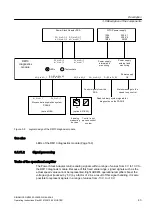
①
X11 – X14
Gating of the power semiconductors, inverter phase u
②
X15, X16,
Gating of the power semiconductors, crowbar
③
X31 – X34
Gating of the the power semiconductors, inverter phase v
④
X35, X36
Gating of the power semiconductors, braking chopper
⑤
X51 – X54
Gating of the power semiconductors, inverter phase w
⑥
X241, X242
Selecting Safe Torque Off
⑦
X70 – X79
Actual value channels 0 to 9
⑧
X81
Trip line
⑨
X200 – X202
DRIVE-CLiQ interfaces
⑩
X231, X232
Analog and digital outputs
⑪
S5.0
S5.1
Switches of the analog inputs, voltage/current measurement AI0
Switches of the analog inputs, voltage/current measurement AI1
⑫
X221, X222
Analog and digital inputs, temperature sensor connections
⑬
LEDs
Diagnostics via LEDs
⑭
X210
Electronics power supply
Figure 3-4
Overview of PSA interfaces
3.5.3
Terminal Modules
The Terminal Modules are the central interface for digital and analog inputs and outputs. You
can optionally expand the interface to include additional Terminal Modules.
Description
3.5 Description of the components
SINAMICS GM150 6SL3835-2LN44-2AA0
36
Operating Instructions Rev.201910281250 MUSTER
Summary of Contents for Sinamics GM150 6SL3835-2LN44-2AA0
Page 2: ...28 10 2019 12 50 V32 00 ...
Page 232: ...Index SINAMICS GM150 6SL3835 2LN44 2AA0 232 Operating Instructions Rev 201910281250 MUSTER ...
Page 233: ......
Page 236: ......
Page 238: ......


