


①
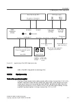
Block diagram of phase module
②
Example: Phase module
Figure 3-3
Phase module
The DC link capacitor bank is connected to the individual phase modules using busbars.
3.3.4
Gating
The gating group and the GCT (Gate-Commutated Thyristor) power semiconductor together
form a fixed unit, the IGCT (Integrated Gate-Commutated Thyristor).
The power semiconductors are connected via the gating boards. The gating command is
transmitted from the power stack adapter (PSA) to the gating board via a plastic fiber-optic
cable connection.
3.4
Operating principle
A constant DC-link voltage for the Motor Module is generated from the line voltage. The Motor
Module provides the power for the connected motor via the DC-link voltage.
The DC link capacitors smooth the voltage and stop the energy in the DC link. The DC link
capacitors are maintenance free and self-healing. The device is switched off when the circuit
breaker is disconnected/opened. The DC link is discharged by means of balancing resistors.
Description
3.4 Operating principle
SINAMICS GM150 6SL3835-2LN44-2AA0
34
Operating Instructions Rev.201910281250 MUSTER
Summary of Contents for Sinamics GM150 6SL3835-2LN44-2AA0
Page 2: ...28 10 2019 12 50 V32 00 ...
Page 232: ...Index SINAMICS GM150 6SL3835 2LN44 2AA0 232 Operating Instructions Rev 201910281250 MUSTER ...
Page 233: ......
Page 236: ......
Page 238: ......


