


Analog modules
9.3 SM 336; F-AI 6 x 0/4 ... 20 mA HART
Fail-safe signal modules
270
Installation and Operating Manual, 01/2010, A5E00085586-10
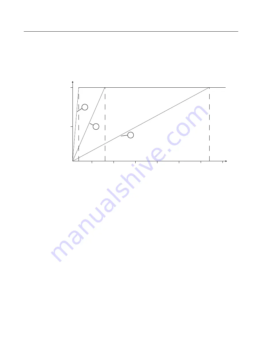
Example
The figure below shows the number of cycles, depending on the smoothing setting, after
which the analog value is completely smoothed and available in the case of a unit step. The
figure applies to all signal changes at the analog input.
6LJQDOFKDQJH>`
0RGXOHF\FOHV
6WHSUHVSRQVHIRUDQ\DQDORJLQSXWVLJQDO
①
Smoothing - 4 conversion cycles
②
Smoothing - 16 conversion cycles
③
Smoothing - 64 conversion cycles
Figure 9-38 Example of effect of smoothing on step response
Example: Effect of smoothing on the maximum response time with 1oo2 evaluation with error
If an error occurred during 1oo2 evaluation, the maximum response time is calculated
according to the following formula:
Maximum response time (in case of discrepancy) = 2 × Conversion cycle time × Smoothing
+ Discrepancy time + 2 × Conversion cycle time
Where N represents the number of activated channel pairs
Example: one channel pair connected (N = 1), interference frequency 50 Hz, smoothing = 16
conversion cycles, discrepancy time = 2000 ms:
Maximum response time (in case of discrepancy) = 2 × 125 ms × 16 + 2000 ms + 2 × 125
ms = 6250 ms
If a discrepancy exists between the two redundant input channels, it can take 6250 ms until
the module signals the discrepancy error to the F-CPU (diagnostic interrupt is enabled).
If the discrepancy time expires, an error is signaled and the process data is set to 7FFF
H
. In
S7 Distributed Safety, the fail-safe value 0 is provided in the PII for the safety program in
place of 7FFF
H
.


