PLC device configuration
6.1 Configuring the operation of the PLC system
S7-200 SMART
System Manual, V2.3, 07/2017, A5E03822230-AF
139
To set an input delay, follow these steps:
1.
Select the time of the delay from the drop-down list beside one or more inputs.
2.
Click the OK button to enter the selections.
WARNING
Risks with changes to filter time for digital input channel
If the filter time for a digital input channel is changed from a previous setting, a new "0"
level input value may need to be presented for up to 12.8 ms accumulated duration
before the filter becomes fully responsive to new inputs. During this time, short "0" pulse
events of duration less than 12.8 ms may not be detected or counted.
This changing of filter times can result in unexpected machine or process operation,
which may cause death or serious injury to personnel, and/or damage to equipment.
To ensure that a new filter time goes immediately into effect, a power cycle of the CPU
must be applied.
Pulse catch bits
The S7-200 SMART CPU provides a pulse catch feature for digital input points. The pulse
catch feature allows you to capture high-going pulses or low-going pulses that are of such a
short duration that they would not always be seen when the CPU reads the digital inputs at
the beginning of the scan cycle.
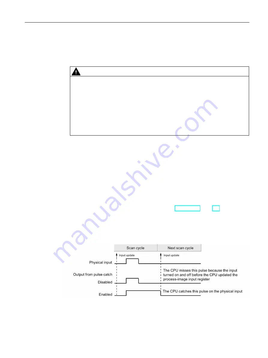
When pulse catch is enabled for an input, a change in state of the input is latched and held
until the next input cycle update. This ensures that a pulse which lasts for a short period of
time will be caught and held until the S7-200 SMART CPU reads the inputs.
You can enable individual pulse catch operation for the first fourteen digital input points (I0.0
through I0.7 and I1.0 through I1.5), dependent upon the CPU model (Page 18).
If your configuration includes an SB DT04, you can enable the two additional digital input
points available on this signal board for pulse catch operation.
The figure below shows the basic operation of the S7-200 SMART CPU with and without
pulse catch enabled:


