


MOBILETT Plus HP
SPR8-220.061.03
Page 6 of 10
Siemens AG
Rev. 03
09.03
CS PS 24
Medical Solutions
9 - 6
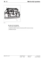
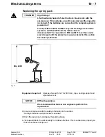
Replacement and repairs on the collimator
•
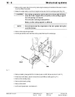
Remove the collimator by loosening the four screws "E" (Fig. 8). Reserve the hardware.
•
Install the new collimator. Center the rotary-flange so that the screws marked "E" are
centered in the grooves before tightening.
•
Connect the wires to connection terminal board "D".
•
Replace the cable ties (Fig. 8). The cable ties have to be mounted exactly as shown in
Fig. 8, Fig. 10 and Fig. 11. The cable ties should not be tightened hard. Fig. 10 and Fig.
11 show how the cable tie on the right side is mounted. Repeat for the left side, but with
the cable tie mirror-inverted.
•
Reconnect K71 to board D70 (Fig. 8).
•
Replace the five cable ties shown in Fig. 9. Make sure they are fastened exactly as
shown in the figure.
•
Rotate the collimator through the whole interval and make sure the cable ties do not
come in contact with the collimator / moving parts.
•
Reattach collimator cover "C".
Do not to forget to attach the cable ties!
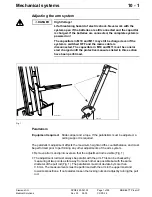
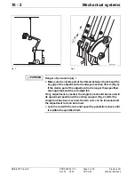
When replacing the collimator, the new collimator should be
positioned and adjusted so that the light and radiation fields
correspond.
The adjustment should be performed by moving the whole
collimator, not just by changing the position of the collimator
bulb.
MOB0057
Fig. 10
MOB00579
Fig. 11
NOTE
NOTICE


