K3R072 Mimic Display board
85
Siemens Building Technologies
007831_a_en_--.doc
Fire & Security Products
03.2004
22
K3R072 Mimic Display board
22.1 Overview
Option to control console B3Q700, or to LON/Mimic Display converter K3I050
2x24 outputs for LED activation for Mimic Display panels, or not monitored relay
contacts (K3G060)
2 control outputs for local ’Buzzer’ and ’LED operation’
2 inputs for ’Switch-off buzzer’ und ’Lamp test’
The lamp test is integrated in menu function B3Q700
Individual allocation of the individual outputs
Max. 24 units, however max. 8 addresses
Communication is via a special serial bus
Line and device not monitored
22.2 Application
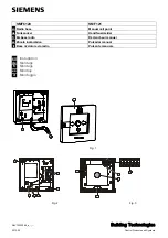
The Mimic Display board is built into the mimic panel housing.
–
Connection to LED via flat cable F50F410 (50-wire, 24 red LEDs, cable length
1m, must be ordered separately)
–
The relay card K3G060 can be connected instead of LEDs
–
Line length data bus B3Q700
→
K3R072 max. 1000m
Connection line
–
Data bus:
via flat cable or 6-wire cable
–
Supply 24V:
via 3-wire cable
22.3 Key
data
Operating voltage
9...45VDC
Current consumption
at 24V
at 9V
at 45V
quiescent 40mA
max. 140mA
quiescent 80mA
max. 330mA
quiescent 30mA
max. 90mA
max. permissible length
of the data bus 1000m
Key 'Lamp test'
Key 'Switch-off buzzer'
Buzzer
LED 1....24
Short-circuit proof in-/outputs
only for
housing application
inside
These in-/outputs can be in
parallel with other K3R072
if located in same cabinet
wires 49+50 for 'LED operation'
LED 25....48
wires 49+50 unused
Z3I520
Synoptic display
panel housing
B3Q700
K3R072
K3R072


