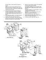
Figure 1
MSI Cover
INTRODUCTION
The Models MSI-30B and MSI-51BD Manual
Stations from Siemens Building Technologies, Inc.,
are addressable devices containing advanced
control panel communication technology. This
technology, which provides two-direction communi-
cation with the control panel, produces an Intelli-
gent Initiating Device.
OPERATION
The MSI-30B/-51BD manual station housing has a
pull down lever that locks in position after releasing
a spring loaded switch (See Figure 3). To indicate
the manual station is activated, the pull down lever
remains down and locked until the station is reset.
The MSI-30B/-51BD is reset by opening the hinged
housing cover with an Allen key and then closing
and locking the cover.
Installation Instructions
MODELS MSI-30B(C) / MSI-51BD
Manual Stations
Figure 2
Wiring Information
Fire Safety
NOTES
:
1. Recommended wire sizes:
18 AWG minimum, 14 AWG maximum
2. Wire larger than 14 AWG can damage the connector.
3.
When using shielded cable without metal raceway or with
nonmetallic raceway,
the shields should be terminated at the device
ground terminal. If the device box is already grounded by another means,
such as being mounted to a grounded structure, then the wire shields
should be continuous and must be grounded solely at the point of origin;
+
+
_
_
TO NEXT
ADDRESSABLE
DEVICE
EARTH GROUND
1
2
3
FROM INITIATING
MXL CONTROL PANEL
OR PREVIOUS
ADDRESSABLE DEVICE
N/C AUX CONTACT
28 VAC/VDC, 0.75A
PIGTAIL LEADS
MSI-30B
+
+
_
_
EARTH GROUND
1
2
3
MSI-51BD
TO NEXT
ADDRESSABLE
DEVICE
FROM INITIATING
MXL CONTROL PANEL
OR PREVIOUS
ADDRESSABLE DEVICE
N/C AUX CONTACT
28 VAC/VDC, 0.75A
PIGTAIL LEADS
The MSI-30B has a key-
switch which can activate
a second address. The
MSI-30B and MSI-51BD
have a set of normally
closed auxiliary contacts
which are available for
releasing door holders
and magnetic door locks.
INSTALLATION
1.
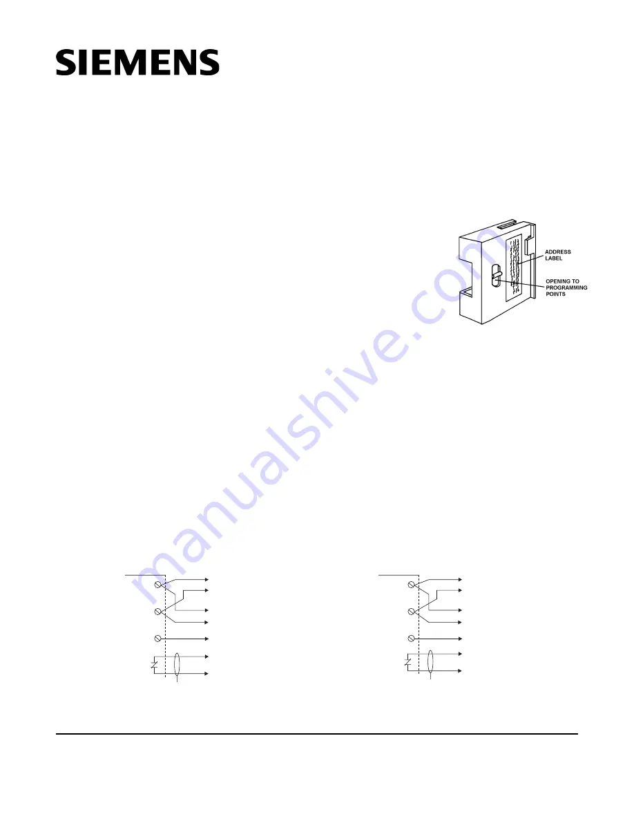
Locate the opening on the MSI cover that allows
access to the programming points on the MSI
printed circuit board. (Refer to Figure 1.)
2.
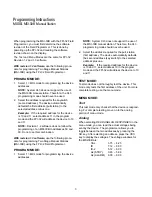
The manual stations are programmed by using the
Model FPI-32 Programmer/Tester. Connect the
MSI-30B/-51BD to the Programmer/Tester by
for example, at the control panel. The device ground terminal shall be
connected to the grounded device box.
4.
When using shielded cable with metal raceway,
the wiring shields shall
be continuous and grounded solely at the point of origin. The device
ground terminal shall be connected to the grounded device box.
5.
When using metal raceway without shielded cable,
connect the device
ground terminal to the grounded device box.
6. Metal raceway should be continuously grounded throughout the system.
P/N 315-099274-3
Siemens Building Technologies, Ltd.
2185 Derry Road West
Mississauga, Ontario L5N 7A6 Canada


