Sensor
Te
V
--
--
--
Test
Test
--
++
++
Digital i n
Digital in
Contrast
Contrast
230V
230V
or
or
115V
115V
ServiceService
++ --
Analog out
Analog out
Digital out
Digital out
Analog in
Analog in
++
0.. 20mA
0.. 20mA
100
100
0.. 20mA
0.. 20mA
AC/DC 48V
AC/DC 48V
30VA 1 A
30VA 1 A
40..60Hz
40..60Hz
Fuse
Fuse
2,5AT 250V
2,5AT 250V
PE N L1
PE N L1
RS
232
RS
232
Data
Data
valid
valid
Limit
LimitTest
Test
Service
Service
Power CAN
Power CAN
+24V
+24V
+ -
H L GND
+ - H L GND
Power +24V
Power +24V
Sensor
Sensor
+
+
1
2
3
4
5
6
1
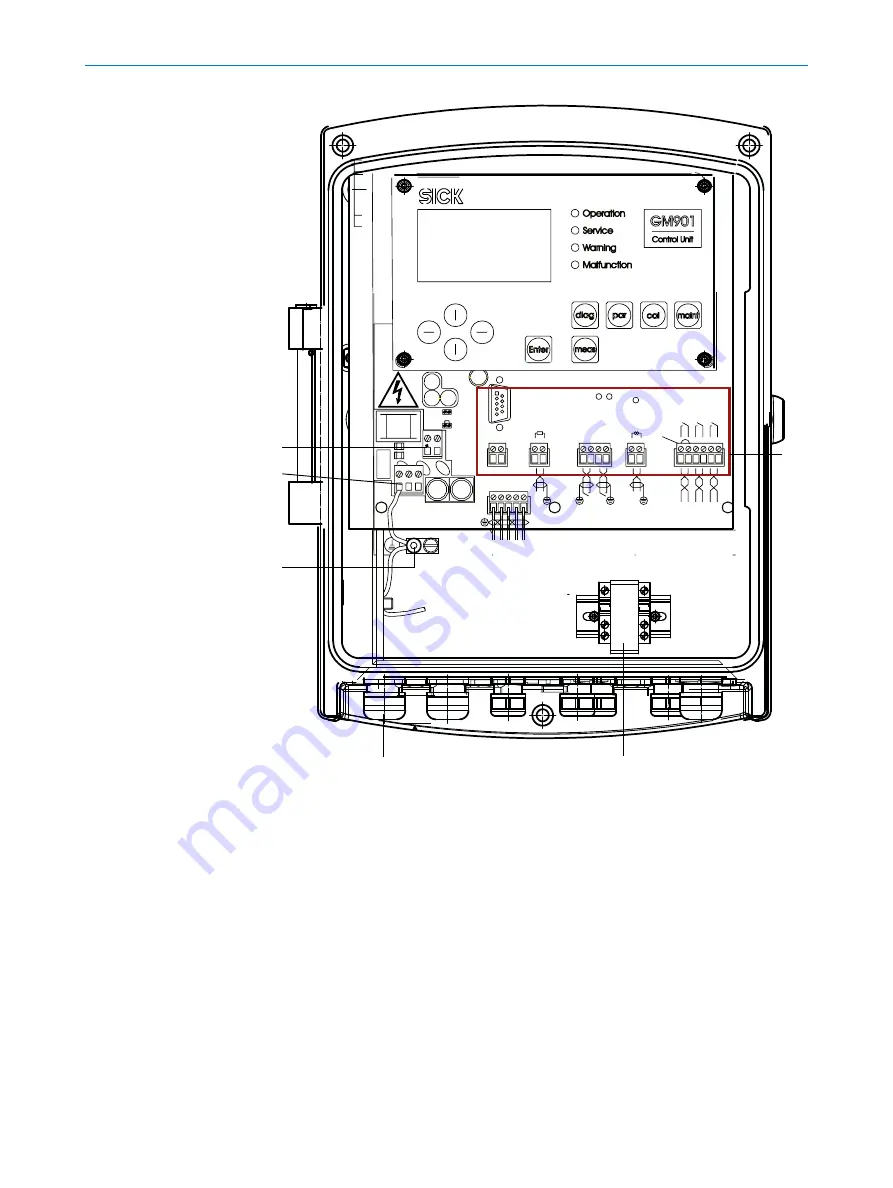
Cable bridge: Operating voltage selection:115 V or 230 V
2
Power supply: 115 V / 230 V
3
Potential equalization connection
4
Screw cap for power supply cable
5
Measuring transducer for PT1000 -> 20mA
6
Terminals for wiring by customer
Connect new measuring probe to control unit AWE (cast metal enclosure)
For new probes delivered after November 15, 2019, the connection is made to the
analog input and not to the temperature transducer.
Connecting the measuring probe
b
Connect the white wire to 24 V GND.
b
Connect the brown wire to analog input (right terminal).
b
Connect the jumper cable between the +24 V terminal and the left terminal of the
analog input.
ANNEX
15
8008932/16YT/V4-0/2022-02 | SICK
O P E R A T I N G I N S T R U C T I O N S | GM901-02
99
Subject to change without notice


